Introduction
The report analyses the processes of developing a web application. It covers different aspects of a web application, including the interface, survival guide, frequently asked questions and problem/change modules. The interface modules provide the web application’s actual functionality. The survival guide module is a support aspect with instruction to enable users navigate through the application in case of difficulties and these include the user, IT technician, and service desk agent’s guides. The frequently asked questions section provides answers to common questions from users designed to save current users time and minimise the number of queries sent to the user support desk.
Users, technicians and service agents use the problem or change module to manage problems in the application. The module enables the end user to view current status or initiate new developments. For the service desk officer, the problem module facilitates the process notifying developing incidents to the IT technicians for the necessary support. Finally, the IT technician relies on the change module to make necessary changes and solve the problem. The process in the change module is achieved through four main steps where the user logs the problem, the service desk assigns the problem, and the technician updates and closes the problem.
The Home Page
The home page important foe the web application, as it supports the user, service desk and IT technician to login to the page. The support is possible with the three entities having unique usernames and passwords for logging in. The home page covers the major aspects identified above based on the type of user. Modules on the home page include the survival guide, FAQ, support system and the track process.
The system interface diagrams
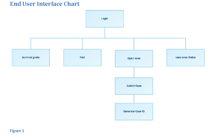
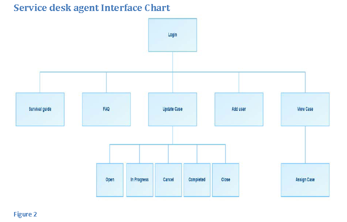
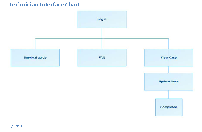
The diagrams below indicate items contained in the end user, service desk agent and technician’s screens. d
Login
The login item provides field for the username and password to offer accessibility of the three users to the application. The login item is programmed to authenticate the login information entered.
Open Case
The open case item enables users to log new incidents to the application using the incident field to fill the problem description.
Submit Case
The submit Case item enables submission of a problem or change to the service desk agent and the technician for further investigation and action.
Generate Case ID
The case ID is the problem identification generated automatically every time an incident develops. The problem ID is important in facilitating the tacking process by users and referencing in case of future calls to the service agent.
View Case status
The view case option supports end users and the service agent to view a case’s progression from the time it is raised to the end.
Update Case
The update Case tab is used mainly by the IT technician and service desk agent to provide updates on the progression or completion of an incident for the end user.
Open case
The tab serves as notification to users that the incident is yet to be assigned and is in line for the assignment.
In progress
The option is an indication of activity on the incident from the service desk to prepare it for assignment to IT technicians.
Cancel case
The cancel option enables the service desk agent to cancel investigation of an incident following notification from the end user of problem solution without necessarily getting support from the system.
Completed case
The incident becomes completed following enactment of the necessary changes by the IT technician and satisfaction of the end user.
Close case
An incident becomes closed following successful solution of the issues raised by the IT technicians.
Add user
The add user option enables the service agent to create new users in the web application.
Use case description
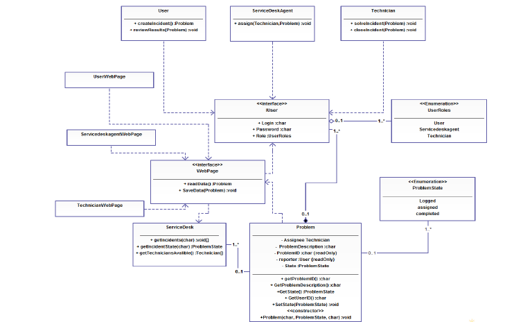
The description offers an explanation for every case in the respective charts. The class diagram description includes the interface user, interface web page, service desk and the problem
Design Techniques – Unified Modelling Language (UML)
The Uniform Modelling Language is important in showing the interaction between the system and users. The language is object oriented and uses graphical modelling to communicate and specify the system dynamics and structure. Unified Modelling Language helps developers in making business models to facilitate business processes through requirements, analysis and design models. In the language, actors include the individual, system or organization interacting with the system. In the graphical modelling, stick figures are drawn to represent system actors.
The UML developed by the Object Management Group helps in documenting specifying and visualizing system models, which include the design and structure meant to address the system requirements. The language provides means for determining system needs and suggests solutions to achieve such requirements. Users can understand system outcomes through the language’s ability to use graphical representation.
Regardless of the approach used to perform system analysis, the language delivers results because it does not depend on the methodology used for analysis. UML uses twelve diagrammatic representations in showing analysis outcomes with four representing the static structure, three for organizing and managing the application, and five to represent the application’s dynamism. Structural chart includes the class, object, component and deployment diagrams. Behavioural charts include use case, sequence, activity, collaboration and state charts. Model management charts include subsystems, models and packages for the system.
The use case chart helps in representing the interaction between the system and system actors and it falls under behavioural chart that includes functions visible to the user. The chart shows the modelling in the system and users easily understand boundaries in the application. Below is a diagrammatic illustration of actors in the system, including the technician the manager and user.
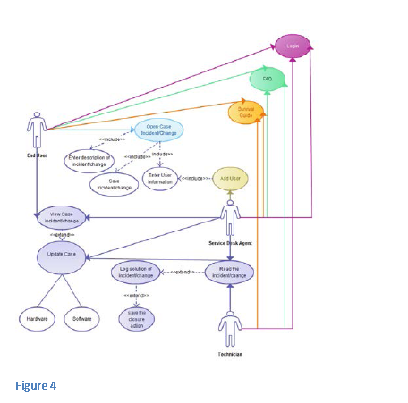
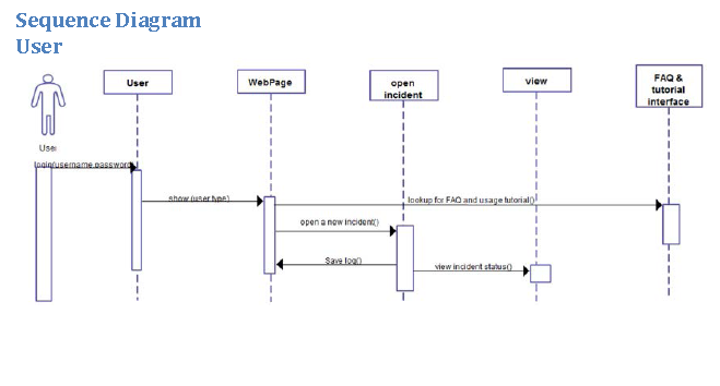
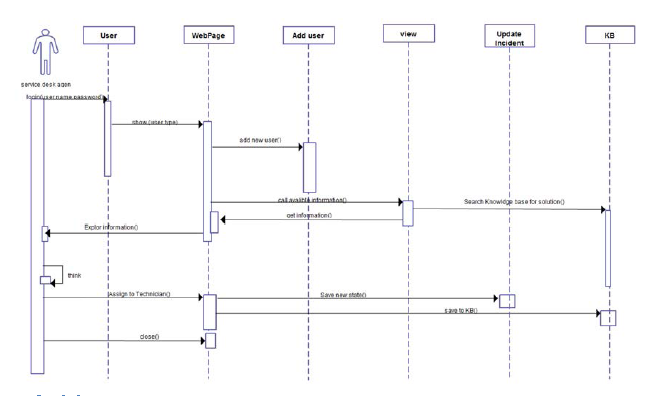
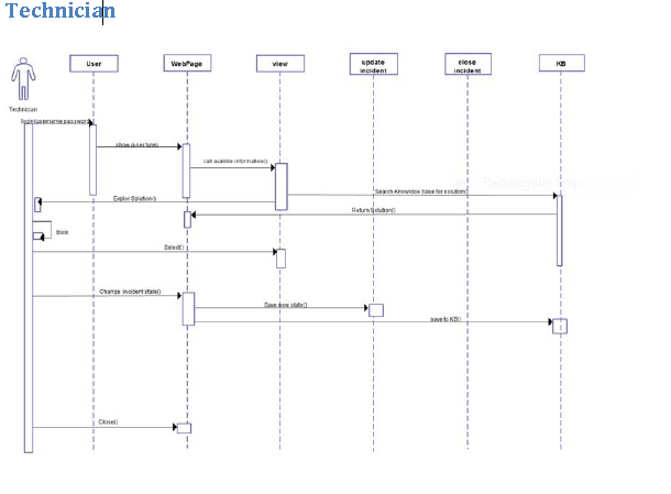
The diagrammatic illustration of the use case highlights all processes or cases in the system as performed by the end user, the agent and technician. From the chart, the end user uses the system to seek a solution for a problem. First the user uses the frequently asked questions module and survival guide to solve the problem. In case the problem is not solved, the user goes on to log it in. After logging in the problem the user has provisions to check its progress status, such as waiting for a response, in progress or closed. The service agent can view the problem from the user, assign it to technicians and provide updates to the system on its status. Complete attention to the problem results in closure. Closure provides room for the service desk agent to add another user to the system and the process goes on.
Interface user
The user interface has three sections for user’s username, password and designation in the system, including technician, service desk agent or end user. The interface enables conduction of different functions between users. The interface enables the user to feed a problem in the application and view its progress. The service agent can assign problems to technicians and the technician can offer the actual solution to the problem assigned. In fact, the manner in which problems are communicated greatly determines how they are solved to improve project outcomes.
Interface web page
The interface web page interprets the data fed by various users and makes it understandable to them. The interface has three possible outcomes depending on the need among the end user, agent or technician.
The service desk
The service desk is the central module in the system and works with the system database. The service desk saves changes and retrieves information from the database according to user needs.
The problem
The problem has a description of the query and its origin with different status from querying to completion. Operations possible with the problem include retrieving its features, assigning to IT technician and changing its status.
Activity chart
A problem in the system exists because of its creation by the user. Following creation, the problem awaits assignment to the IT technician. Following assignment, the state of the problem changes to ‘assigned to a specific technician’. The problem remains under the technician until it is solved. Following successful solution, the problem status changes to ‘completed’ and the next activity is saving to the system. The chart below shows the problem activity.
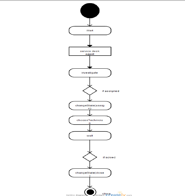
Categorisation of the problem
Any problem raised by the user falls into the broad category of hardware or software problem with an example of problem description and the resolution period shown in the table below.
The physical design
This is a reflection of the physical aspect in implementing the system design. An example of a physical design includes designing system corresponding to the database design.
The database design
The incident and account detail tables are important in storing data in system applications. The incident table is important for storing information following opening of a new case. The table has four rows to store fields in the case, namely the field name, field type, maximum length and the primary key. The account detail table stores the user’s information in the system application and it has fields, including the field name, field type, maximum length and the primary key.
Software requirements for system design
Hypertext precursor
PHP is a specific software designed for web application used on by servers as a scripting language. The language is dynamic and it enables developers of web applications to write dynamic content. PHP has the advantage of being the interface to various databases such as Microsoft products, the Oracle and MySQL, which provide open database connectivity (ODBC). The software is openly available and programmers acquire it at a low cost. PHP supports portability in different platforms with its open source technology based on Java, Perl and C supporting usage on several web servers and operating systems.
MySQL
The MySQL language is a relational management system for databases and works as an open source. As the name suggests, MySQL applies Structured Query Language. The system develops prefer MySQL for adding, accessing and using data from databases. Preference for the language is based on it being fast, scalable and vigorous as a relational management system for databases. The language enables the use of multiple threads and supports multiple users at the same time.
Apache web server
This server is responsible for responding to user requests for resources, including the XHTML resources. The Apache application comes with a set of modules such as the mod Perl, and authentication applications to support systems.
Microsoft Visio professional 2010
The software developed by Microsoft enables the creation of UML charts, including sequence charts and use case charts. The charts are important in making representation for various systems.
Microsoft Office 2010
The application developed by Microsoft helps in performing several tasks including monitoring the progress of projects, estimating costs, monitoring projects and preparing Gantt charts.
Adobe Photoshop
The application helps in the creation and management of images among other processes required by web developers and users.
Hardware requirement for system design
The server
The server is a major component of any system development because it is the main part that enables control of the system by the administrator or programmer. Examples are servers used in universities to manage various functions.
The Client
The client enables installation of different applications, for example, the Pentium-based personal computers.
The Software Test Plan
This plan provides a thorough description with regard to the schedules, approaches, resources and the extent to which the various software components withi the system could be tested. Through the software test plan, system developers identify critical items for testing, specific features to look for in testing, the kind of testing to perform, specific individuals for conducting the test, as well as the schedule and resources necessary to accomplish the testing. The software test plan helps systems and developers among other users to achieve three major objectives.
- First, the test plan supports achievement of codes that are 100% correct and confirm that all requirements for system design and functioning are implemented according to specifications in the system documentation.
- Second, the test plan provides procedures for testing systems and units in the systems.
- Third, test plans identify approaches used for testing the stem and units.
The software test plan process
The test plan process involves a series of six steps.
- The first step involves the identification of requirements for testing. Programmers derive all test cases using the current specification for system design.
- The second step requires programmers to identify specific testing for every module in the system.
- The third step involves a review of test case and test data to confirm thorough verification of the unit and to ascertain the adequacy of test cases and test data to confirm proper operation of every unit in the system.
- The fourth step involves identification of the likely outcome for every unit test.
- The fifth step is the actual conduct of the test.
- The final step requires programmers to document the test cases and test data using in the process of testing the system units.
Testing method
In the test plan, there is a comprehensive outline of the process of testing, which includes the specific cases for testing. The test plan is important in planning specific tests for programmers to conduct. During deployment of the system, testing could be carried out to assess the integrity of units, interfaces and integration of various elements.
Unit testing
With regard to unit testing, software designers could conduct assessments to ascertain the level of functioning of the various modules and units within the system. Unit testing may also involve software elements grouped together. It is important to note that assessment of different components within the system is crucial because it helps designers to identify areas that could require corrections and/or improvements. Developers test individual units separately and in some cases collectively depending on their functionality.
Interface testing
Developers perform interface testing of various modules of the system. The modules include the login module, view case module, Add user module, open case module, and update case module, tutorial module and the frequently asked questions module.
Integration testing
Integration method of testing enables developers to test the capacity of the system to work and integrate the MySQL and PHP languages. The system achieves integrity between the languages when updates done using PHP reflect an automatic change on MySQL language.
System testing
The testing is a major step, as it enables developers to ascertain the integrity of the whole system design.
User acceptance testing
If a system is successfully completed and tested, then system developers should conduct the final testing that is aimed at assessing the level of acceptance with regard to the end-users. In this process, users are critical, as they ascertain whether or not the system meets the intended purpose.