Introduction
The investigation reported in this study was carried out to demonstrate mesh and nodal analysis techniques and to validate each procedure experimentally.
Theory
The team systematically broadens their comprehension in this laboratory exercise to evaluate the currents and voltages in circuits with multiple nodes and loops. The analyses are principally based on two topic-related laws: Kirchhoff’s current law (KCL) and Kirchhoff’s voltage law (KVL). Kirchhoff’s current law is used in nodal analysis to calculate node voltages. Similarly, Kirchhoff’s voltage law is employed in loop (or mesh) analysis to calculate loop currents (Wang et al., 2018). The variables in the circuit are chosen to be the node voltages in nodal analysis. The node voltages are indicated at a central location in the circuit.
This node is frequently the one to which the most assortment of branches is connected. It often serves as the chassis or physical earth juncture in functional circuits and is considered at ground zero voltage. Mesh or loop analysis, as contrasted to nodal analysis, deploys Kirchhoff’s voltage law to evaluate currents in the circuit. Ohm’s law can be applied to determine the voltages once the currents have been determined. The network must be described using N independent numerical solution if the circuit has N-independent loops.
Experimental Procedures
List of Components
The following components were required to ensure the accomplishment in this experiment;
- Breadboard
- Resistors (1K, 2.2K, 3.3K, 4.7K, and 5.6K)
- Connecting wires
- Digital Multimeter
- DC power supply
Schematic
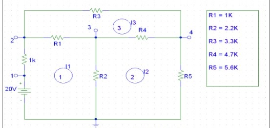
The figure below is the schematic diagram of the circuit involved in this experiment.

Procedure
In mesh analysis, assemble the circuit shown in figure 1 (after checking the Ohmic value of the resistors). Measure the voltage (7 voltage measurements) throughout each resistor and the series configuration of the input voltages and the 1K resistor. Determine the current flowing through each resistor using Ohm’s law. Iab denotes the current flowing through a resistor connecting nodes a and b. Ensure that I12 represents mesh current I1, I40 represents I2, and I24 represents I3. In nodal analysis, determine the node voltages V20, V30, and V40 using the earlier voltages. Evaluate and contrast the two methods of analysis employed in this experiment.
Results
The results of the figure above are presented in the tables below with voltage measurement points.
Table 1:
Sample Calculations
In loop 1:
In loop 2:
In loop 3:
By solving equations (i), (ii), and (iii):
- I1=5.97mA
- I2=1.62mA
- I3=1.51mA
Voltage calculation:
As V1=20V;
At node 2:
At node 3:
At node 4:
Solving equations A, B, and C:
- V2 = 19.08V
- V3 = 9.57V
- V4 = 9.06V
Interpretation
As demonstrated by the result table, there is an unexpected difference between the values obtained when determining node voltages and the simulated values. The node equation derived from an N number of nodes on the given circuit is (N-1) since one node served as a reference node (Wang et al., 2018). The two Kirchhoff’s laws were employed to generate the equations containing the unknown voltages in the case the circuit is a known voltage. After obtaining these equations, the voltages were solved using linear algebra. The major contribution of these errors might be the variances in the resistors or wrong connection of the digital multimeter leading to inaccurate readings.
Conclusion
The objective of this investigation was accomplished, and the results were obtained. KVL served as the fundamental law for mesh analysis, and KCL as the fundamental law used for nodal analysis. Although the values estimated for the currents and voltages for both the mesh and nodal analysis seem to be varying compared to the results obtained, the two Kirchhoff’s laws were validated experimentally. The two methods can be applied together to understand a complex circuit.
Reference
Wang, Y., Zhang, G., Zhang, S., Wang, Y., & Xie, X. (2020). Analysis and simulation of multi-loop SQUID-based electric circuits with mesh-current method. IEEE Transactions on Applied Superconductivity, 30(8), 1-9.