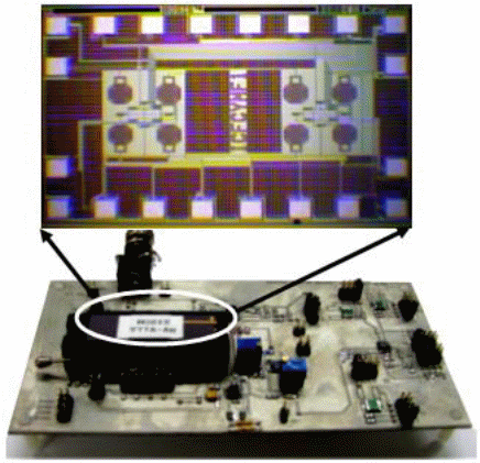
The micro-system system is wholly automated, and it is used in biomedical functions. This system entails two core parts:
- ACMOS Integrated Circuit, which entails the detecting and triggering sections.
- A control circuit board, which involves the intensification and the conditioning sections. This system is an appropriate entrant for biomedical purposes like noninvasive cell exposure, cancer sensation, and selection of antibodies (Gallab 1027).
DeFET’s principle of working
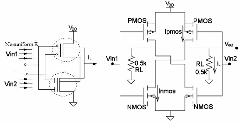
DeFET contains two FETs, which include the P-type and the N-type. A cross-coupling occurs between the two drains of the FETs and the gates are floated and connected to one other. When E is applied over the DeFET sensor, then E=Vin1-Vin2/d. The differential voltage Vdiff is equal to the product of the applied E and the distance between the split gates (d) Viff=Vin-Vin2=Ed. Also, IL= Ipmos- Inmos, where IL is the load current, Ipmos and Inmos is the drain currents from their respective FETS (Gallab 1033) (Gallab1035).
Sensing
When E is produced, then the applied E is a function of d. E can be detected using DeFET by measuring Vout, which is the intensity of the applied E (Gallab1028).
Actuation
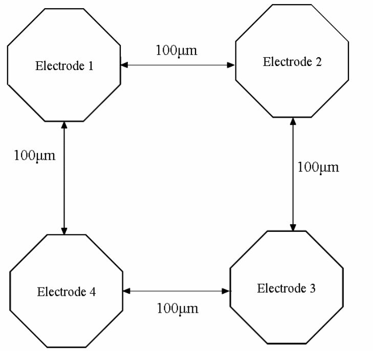
It is made up of four electrodes:
- The electrodes maintain passive stable particle levitation.
- They give a strong E force so that small particles can be levitated (Gallab1030).
Multiplexer
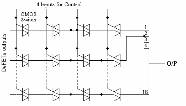
It is a 16*1 analog multiplexer used to multiplex 16 DeFET sensors outputs. It consists of transmission gates and four control terminals. A certain output value of DeFET can be obtained by applying the equivalent combination of four digital control signals. Additionally, by applying these four control terminals of the multiplexer with a 4-bit counter output, all 16 DeFETs can be scanned continuously, which is a crucial characteristic feature for the applications(Gallab 1034).
Fully automated CMOS micro-system board
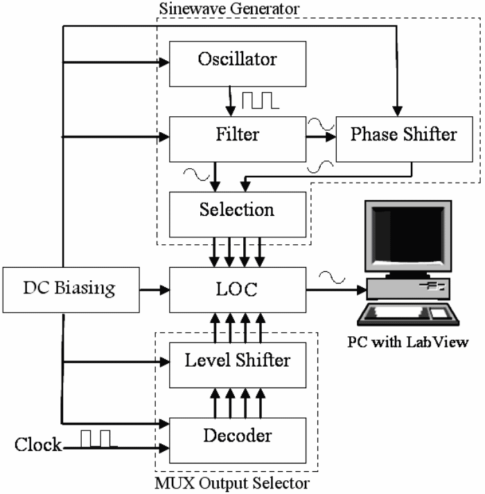
It is made up of
- An oscillator, which, produces a square waveform with frequencies ranging from 1MHz to 10 MHz.
- A filter: to filter the output of the oscillator.
- Phase shifter: used for inverting the input at a gain of -1 and below.
- Selection part: It consists of 8 switches. It obtains its inputs from the phase shifter and the filter, and it can spread these signals into the inputs of the quadruple electrodes.
- Decoder: it a 4- bit counter, which, obtains its input from the clock at a given frequency. It controls the multiplexer’s nonstop scanning on the 16 DeFET detectors.
- Level shifter: it varies the output of the counter to obtain1.8V for the multiplexer. Lab-View: it is a visual programming language development (Gallab 1035).
Electrical Testing
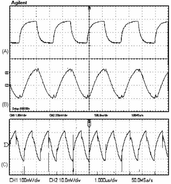
The micro-system is tested at various frequencies like 1MHZ, 2.8MHz, and 8.6MHz. Fig. 6 below shows the output of various sections of the board at 1MHz (Gallab 1036).
Biomedical Testing
The system is tested at 819.7 kHz with Hemolymph, which is obtained from the snails. Gallab1037).
Conclusion
The LOC can actuate the electric field E and sense it in real-time, which is an important merit in the LOC prototype. The micro-system can be used in the biomedical lab- on- chips, environmental monitoring by sensing particles in the air, and detection of scratches.
Works Cited
Gallab, Ballawy (2006) “A novel electric field sensor for lab-on-chip for biomedical applications”: IEEE Journal of sensors 6.4 (2006):1027-1037. Print.