Introduction
A truss may be defined as a fabric of beams or posts forming a fixed structure that holds up a bridge, roof, or another structure. Roof trusses are normally triangular-shaped structures that give stability and support to the roof. They also play the role of distributing the roof’s weight away from the outside walls of the building or the structure involved. Trusses can support heavy loads without adding extra weight to the overall mass of the structure. In residential design, trusses are commonly made from wood. For commercial building design, steel trusses are mostly used. Trusses take the triangular shape because of the shape’s natural ability to dispel pressure throughout the whole structure making it highly stable and rigid (Ambrose, 1997).
Methods of finding the internal forces
Before analyzing methods of finding internal forces, it is important to note that we do have statically indeterminate structures and statically determinate ones. The latter can be analyzed using equations of equilibrium only while the former needs more than these equations to solve it (Somayaji, 1990). A statically determinate truss that has two reactions must satisfy the mathematical equation 2j=m+3 where j represents the number of joints, and m is the number of members in the system. Statically determined trusses can be easily analyzed by the use of the method of joints. Statically indeterminate structures do not satisfy the above-stated equation. Static indeterminacy of planar trusses which are static may be evaluated using the mathematical operation i= (m+r)-2j where m is the number of members, j represents the number of joints, and r shows the unknown reaction components. The number of redundant reactions must be identified and be equal in the degree of indeterminacy. When the selected redundant is directly proportional to the restraints, then the truss resulting is statically determinate stable.
Method of joints
In this method, we do pick a joint that does not have more than two unknowns and then solve using rules of equilibrium. With the aid of a free body diagram of each joint, the unknown forces at that joint are solved. In this method, you need a Free Body Diagram of each joint and hence solve for the unknown member forces at that particular joint. Once, this joint is completed, move to the next one and solve it. This analysis of joints is done throughout the whole truss and, thus, solves for the force in all the members. A free-body diagram of the whole truss is drawn as the first step, and the external reactions are found if they are required. This is followed by selecting a joint that has only two unknowns, and the roller joint may be the best starting point. The third step is to draw a free body diagram of the joint in question and solve the internal forces with the help of a force polygon. The forces involved here are concurrent and might be either compression or tension forces. The forces found are then transferred to the adjacent joint. Having done these, we go back to our second step, choose a joint with only two unknowns once again, draw the respective free body diagram and solve the internal forces involved until we exhaust all the joints on the truss. It is important to note that if you had assumed a force to be tensional, but it turns up to be negative, then that force must be compression, hence analyzed that way. Having known a force on one end of the member, then, the same force is in the opposite direction on the other end. This is because the force would have been rotated through a half angle. This method is of importance when one is designing a structure and would like to know the forces in every individual member. It is also good to note that with an increase in the number of joints, the number of equations to be solved also increases. This will introduce more arithmetic work which may be prone to errors. At this point, computer programs should be used.
Method of sections
This method banks on the fact that the truss is in equilibrium, then all the sections of the truss must be in equilibrium including when the truss is cut into half if one desires. It is a speedy way for one to find the stresses found in the middle of a complex structure of a truss. Hence there will be no need of solving every joint. This implies that one can just cut the truss into a half and then make a free body diagram of one of the halves. One must ensure that the half which he has thrown away has been replaced by the forces it was applying on the free body diagram. When this is done, then the internal forces are solved by the equilibrium equations, and the point from which moments are taken should be carefully chosen. As explained earlier, we may first solve for the support reactions of the whole truss if required. This is followed by cutting the truss halfway through the member you would like to know. A free-body diagram for the half which is sectioned is then drawn while substituting the cut-off members with respective forces. The next step is to formulate a moment equation by taking moments around the point of intersection of two or three forces that are unknown so that we can be able to find the third one. If it is necessary, then solve the equilibrium equations to find the rest of the other members through the section. It is important to note that the method of sections is employed when one wishes to analyze middle members of a complex truss.
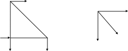
Consider the isosceles right-angled triangular truss shown below and its free body diagram shown beside it in respect to point b which is at the vertex of the y axis.

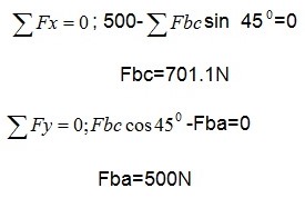
All the forces shown by arrows are 500N each. Joint b is not moving hence at static equilibrium. This means that there are no unbalanced forces for both x and y direction.

In the analysis truss structures, one must bear in mind that they may be designed in a manner that its members will carry the loads in either tension or compression. In most cases, all the loads are applied at the joints. In summary, trusses are just efficient and able to support large loads by distributing the force throughout to all the members. They also cost less, have more mechanical advantages and exert less stress on the supports. This explains why they are widely used in the building industry.
Works Cited
Ambrose, James. Simplified Design of wood structures. Hoboken, NJ: Wiley Pulishers, 1997. Print.
Somayaji, Shan. Structural Wood Design. NewYork: Random House, 1990. Print.