Introduction
The investigation reported in this analysis was conducted to validate whether Kirchhoff’s Voltage Law was effective. Three resistive circuits were built to test Kirchhoff’s voltage law. The sum of voltages across various closed routes in each system and the sum of the currents at different nodes were measured.
Limitations
The experiments are limited because they operate under the hypothesis that the electromagnetic force in the closed loop system is constant. Kirchhoff’s loop criterion can be disobeyed in the presence of a fluctuating electromagnet field because electric fields and electromotive fields can be produced.
Theory
The theoretical basis of this investigation was evaluating the sum of the voltage drops throughout various closed connections, which is equal to zero. The preliminary work required was understanding the concepts of homogeneity and additively and using the digital multimeter to determine the resistor values.
Experimental Procedures
Schematic
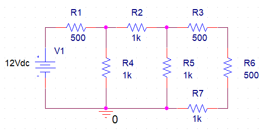
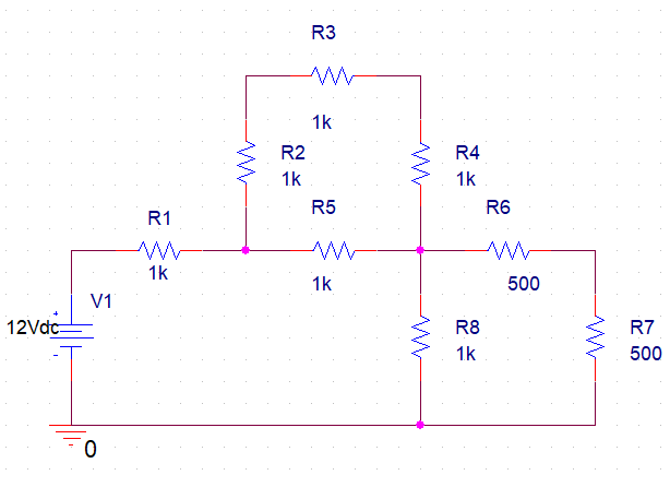
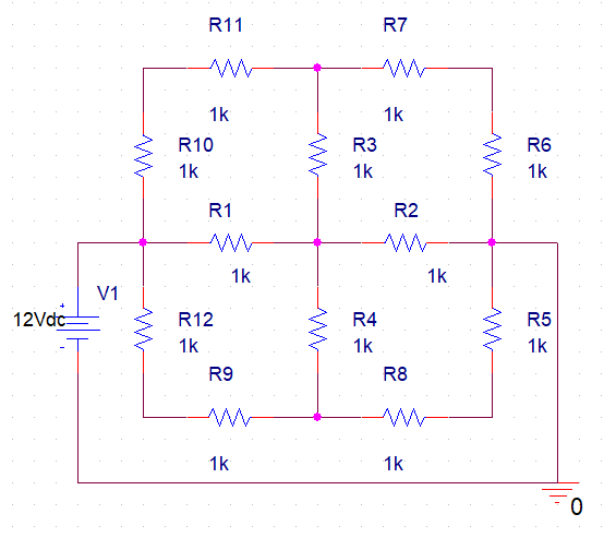
The three figures below are the schematic diagram of the circuits involved in these experiments.


Procedure
Identify all voltage measurement nodes and execute the voltage calculations. Constructing the circuit is illustrated in Figures 1, 2, and 3. Use laboratory apparatus to measure voltage. Every measurement must be made in relation to the ground.
List of Components Used
- Breadboard
- Resistors
- Connecting wires
- Multimeter
- DC power supply
Results
The results of the figures above are presented in the tables below with voltage measurement points.
Table 1
Table 2
Table 3
Sample Calculations
Experiment 1
IR =V
I1 (500+625) = 12V
I1 =0.01A
V1 =0.01A×500Ω
=5.0V
V2 =0.01×625
=6.25V
I2 =6.25V÷1000Ω
=6.25mA
I3 =0.01-6.25×10-3
=3.75mA
6.25-V3 = (1K) (3.75mA)
V3 =2.5V
I4 =2.5V÷1000Ω=2.5mA
I5 =3.75mA-2.5mA
=1.25mA
V4 =3.75mA×1000Ω
=7.5V
V5 =500Ω×1.25mA
=0.625V
V6 =1000Ω×1.25mA
=1.25V
Experiment 2
I =12V÷ (1000+750+500) Ω
=5.33mA
V4 =12-(5.33mA×1000Ω)
=6.67V
V5 = (12V×500Ω) ÷ (1000+750+500) Ω
=2.67V
V6 = (2.67V×500Ω) ÷ (1000Ω)
=1.335V
5.33mA =3I2+I2
I2 =1.3325mA
V42 =1.3325mA×1000Ω =1.3325V
V45 =6.67V-2.67V =4V
V45 =3V42
4V =3V42
V42 = (4÷3) V =1.667V
V2 = (6.67-1.667) V
=5V
V3 = (5-1.667) V
=3.33V
I =2I4
I4 =5.33mA÷2
=2.605mA
V7 = (2.667×10⁻³A) (1000Ω)
=2.667V
Experiments 3
V1 =12V, V3 =0V
At node 2,
4V1-V5-V8-12 =0 … (1)
At node 1,
2V2+V5-V8 =48 … (2)
At node 8,
V2-2V8-6 =0 … (3)
From (1) and (2),
7V8-V5 =36 … (4)
Adding (2) and (3),
5V8+V5 =60 … (5)
Adding (4) and (5),
12V8 =96
V8 =8V
V5 =-5(8) +60
=20V
V2 =2(8)-6
=10V
V7 =12-[(12-V8)/2]
=10V
V4 =12-[(12-V5)/2]
=16V
V6 =V5-V5/2
=10V
V9 =V8-V8/2
=4V
Interpretation
The experimental measurements were much higher than the expected results from the calculations. The values were not precisely zero when combined. However, this was anticipated due to experimental error when connecting several components. The idea that series voltages added up made no difference, but from observation, the polarity of these voltages significantly affects how the numbers are added. Since the polarities of each voltage drop are in the same direction (Salam, & Rahman, 2018). Although the cause of this discrepancy is uncertain, the wrong connection of the multimeter might have contributed to giving inaccurate readings. Variability in the resistor and voltage source values was another factor that might have caused errors in circuit measurements.
Conclusions
In summation, in a complex circuit where all voltages around a particular loop are known, Kirchhoff’s voltage can be employed to determine an unidentified voltage. The law failed to predict the total sum of the voltage drops along closed circuits under consideration due to experimental errors.
Reference
Salam, M., & Rahman, Q. M. (2018). Electrical Laws. In Fundamentals of Electrical Circuit Analysis (pp. 25-73). Springer, Singapore.