Introduction
A corpuscular-wave duality of photons creates unique optical and quantum properties of light, which can be observed experimentally. According to the laws of optics, in a transparent homogeneous medium, light propagates in a straight line, forming rays; the set of such rays is called a light beam.
Strictly speaking, the light beam is also correctly understood as light radiation, which is distributed from some point in space and is either divergent or convergent, depending on the direction vectors of light beams in the beam (Fig. 1). It is noteworthy that the propagation of the light beam in the medium does not depend on whether there are other beams in this medium, which forms the law of independence of light beams. Artificial sources of the formation of light beams are lamps, floodlights, lighthouses, and laser installations — in all these cases, the device forms a set of light beams with a similar spatial structure and configuration.

The Property of Diffraction
Meanwhile, the light beam remains a wave, so it is capable of demonstrating all the characteristics characteristic of waves, including the ability to diffract. In general, diffraction is the deviation of a wave from the trajectory of rectilinear propagation of light when passing near some obstacle. In simple words, diffraction is the phenomenon of rays bending around an obstacle with their consequences. Diffraction studies the distribution of light intensity on the screen after passing an obstacle — from the diffraction pattern, it becomes possible to judge the properties of the beam falling on the obstacle. In fact, in the diffraction of any waves, including light waves, visual observation of the envelope of obstacles by waves is possible only if the dimensions of these obstacles are comparable with the dimensions of the wavelengths.
If the dimensions of the obstacles are significantly larger or significantly smaller than the corresponding wavelengths, then the envelope of the obstacles will not occur; a shadow is formed. In contrast to the large wavelengths discernible by the human eye, the wavelengths of visible light are critically small, so the phenomenon of diffraction for a beam of light is not easy to observe. For a diffraction pattern to be obtained, slits of minimum size comparable to the wavelengths of the light beam are required. Furthermore, passing a beam of light through a small hole in a wall allows a spot more significant than the initial beam to be obtained on a screen behind that wall. Thus, there are uncertainties and complexities regarding the diffraction of light beams that should be discussed.
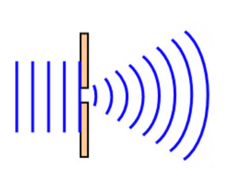
An essential contribution to the understanding of diffraction processes was made by Fresnel, who developed earlier theoretical concepts of Huygens. Thus, according to the Fresnel-Huygens principle, during the propagation of light, each point of the wavefront becomes a source of secondary spherical waves, which in turn generate tertiary waves. In simple words, each point in space to which the wave reaches becomes the source of new waves. The enveloping curve for these waves forms a wavefront, whether primary or secondary. Notably, all circulating waves turn out to be coherent, which means they can interfere since their phase difference is constant in time. For the study of diffraction, critical knowledge was necessary of the existence of precisely coherent sources.
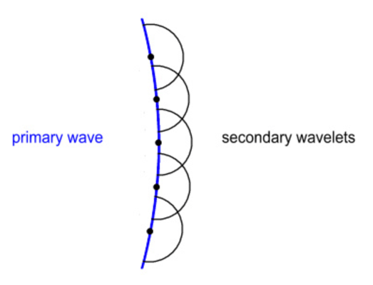
The formation of secondary waves is observed as a result of the diffraction of a light beam on a hole of a small size. Referring to Fig. 4 shows that the primary wavefront is mainly absorbed or reflected by the obstacle materials, and only a tiny part of the front enters the slit. According to the Fresnel-Huygens principle, the edges of this slit become the sources of formation of secondary waves that have coherence, but they cannot interfere because, for single-slit diffraction patterns, there is no intense interference due to the singularity of the secondary wave source. The conclusion seems to be obvious — if one increases the number of slits to two, the coherent waves will begin to interfere, which will allow obtaining a diffraction pattern.
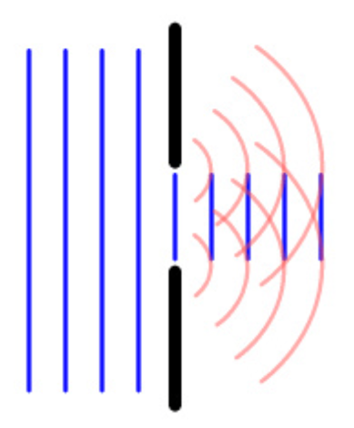
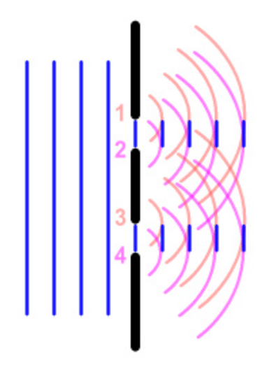
There is no typical diffraction pattern because the particular pattern of the spot formed on the screen after the beam passes an obstacle will be determined by the nature of that obstacle. For example, if only one slit were used, the diffraction pattern would look as shown in Fig. 6. In contrast, if the number of slits is increased to two, the diffraction pattern will be more complex because the interaction of small secondary waves formed from the edges of each of the obstacles will form internal interference patterns so that the final spot will be recursive. There are also diffraction grating obstacles, which are a large number of small slits onto which a light beam is fed. Diffraction gratings are often used in industry because they allow monochromatic light to be isolated as well as split beams. For such gratings, there is a formula that relates the distance between adjacent slits in the grating (d), the incident light wavelength (λ), the angle of incidence (θ), and the order of the diffraction grating (n), namely: dsinsinθ = nλ
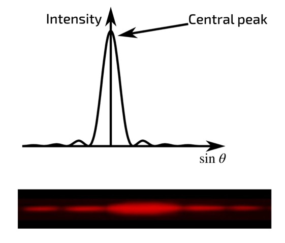
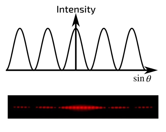
It is interesting to note that there is no distinct difference between diffraction and interference, as both are produced by the superposition of light beams when overcoming obstacles. The superposition of waves leads to the redistribution of their intensities in space. The only difference between interference and diffraction for light beams is the number of sources of coherent waves — for diffraction, this number is theoretically continuous and infinite. In addition, there are different types of diffraction, depending on which rays pass an obstacle. Revisiting Figure 1 shows that there are both parallel and convergent rays; the difference is where the total vector of the entire beam is directed. If diffraction occurs in convergent beams, then they speak of Fresnel diffraction, which is observed at a short distance from an obstacle. For Fresnel diffraction, the number of corresponding diffraction zones is much greater than unity. On the contrary, if the diffraction is observed in parallel beams, that is, when the observer is far enough away from the obstacle, they speak of Fraunhofer diffraction. In this situation, the number of Fresnel zones is significantly less than unity, and the waves coming to the screen are practically flat.
Bessel Beams
It is fair to admit that although most light waves have the ability to diffract, there are exceptions. In particular, a Bessel beam is an electromagnetic wave that does not exhibit a tendency to diffraction and therefore does not change its configuration when propagating in space. Simply put, this means that even at enormous, theoretically, infinite distances, the Bessel beam is focused. Another surprising property of Bessel beams is the ability to self-repair as a result of collisions with obstacles. More precisely, Bessel beams may encounter barriers on the way of their propagation, and a normal wave, in this case, would bend around the obstacle, changing its configuration structure. However, such principles are not true for Bessel beams because even after overcoming an obstacle, the beam is capable of self-restoration. At the current moment, it is clear that the practical existence of such a beam is impossible since an infinite amount of energy would be required for its propagation in space. The cross-section of such a beam represents ideal concentric circles at any moment of time, and therefore it is impossible to create such a beam artificially.
Nevertheless, science has come close enough to obtain some approximation to the ideal Bessel beam model. To create an artificial pseudo-Bessel beam, an axicon lens on which a Gaussian beam is focused is used. It should be additionally noted that a Gaussian beam is understood as such a radiation beam for describing the electromagnetic properties of which a Gaussian function is well used in the cross-section. In addition, the Gaussian beam has a high propensity for monochromaticity, so it is widely used in industrial optics.
The second component for obtaining a Bessel beam is an axicon lens. Strictly speaking, such lenses (or axicons) should be called axisymmetric lenses in which one side surface is flat, and the other is cone-shaped. As shown in Figure 8, when a monochromatic beam of parallel light rays hits the conical surface of a lens, it refracts the light rays into a single point of focus. From the point of view of an outside observer, after passing the axicon, the beam turns into a ring. When the refracted rays intersect, a focused beam is formed in the depth of focus (DOF), located along the optical axis. This beam will be the Bessel pseudo-beam, and therefore this beam will be a combination of conic waves formed by the passage of the monochromatic beam of the axicon lens.
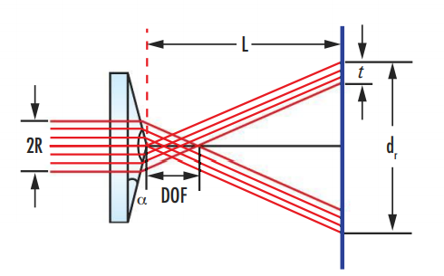
To calculate the Bessel pseudo-beam, the depth-of-focus equation is used, as shown below. In simple terms, depth of focus should be understood as the maximum distance between objects that are in acceptable focus, that is, visually distinguishable. A simplified version of this equation allows determining that the DOF for a Bessel beam depends on the angle of inclination of the conical surface of the lens.
Decreasing the value of this angle causes the DOF to increase. It is noteworthy that in an axicon lens, this angle appears constant for all lateral surfaces, which means that the outgoing rays appear constant in time and space, unlike rays focused by conventional lenses with varying focal angles. In addition, reference to Figure 9 shows that after exiting the axicon lens, the extended nondiffracting beam formed in the overlap zone retains a relative constancy of its transverse properties, which allows considering this beam as an approximation in the Bessel model. This distinguishes the formed beam from the classical Gaussian beam, which does not tend to preserve the amplitude of oscillations as it moves away from the lens. However, the energy still dissipates over time, which confirms the impossibility of instrumentally creating an ideal Bessel beam.
DOF = R√1-n²sin²α/sinα*cosα (n*cos*cosα – √1-n²sin²α) ≈ R/ (n-1)α
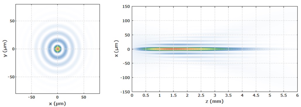
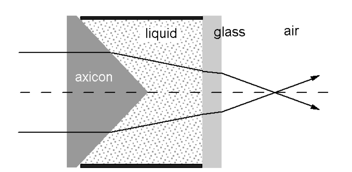
It is not enough to direct a Gaussian beam into an axicon lens in order to obtain high-energy Bessel beams. It is necessary to achieve a situation in which the laser beam emitting a monochromatic Gaussian beam is directed along the optical axis of the axicon lens. In practice, for this purpose, extenders, mounts, and stands are used to control the angle of the laser radiation. When the advantages of using an axicon lens were no longer questioned, researchers began to modify such lenses to improve the properties of the output non-diffracting beams. This led to the emergence of tunable axicons, which change the tilt angle of the conical surface. More specifically, in a tunable axicon device, the lens is placed in a liquid that has a refractive index lower than the refractive index of the material from which the axicon is made, as shown in Figure 10.
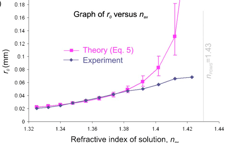
This strategy is due to the desire to refract a Gaussian beam and reduce the effective cosine angle of the Bessel beam — as a consequence, the beam size increases. It is noteworthy that in this configuration, it is possible to change the refractive index of the liquid medium — by using another liquid or by increasing the temperature — and as the refractive index increases, the effective beam diameter also increases almost linearly, as shown in Figure 11. Decreasing the cosine angle is also acceptable when using a liquid medium whose refractive index is critically close to (but not equal to) the material index of the axicon; in this case, the maximum width of the Bessel beam is achieved. In a conventional axicon, which is not based on placing a lens in a liquid, the Gaussian rays are not refracted so much, and, thus, the cosine of the output angle is effectively reduced — the width of the Bessel beam is noticeably lower.
Axicon lenses are widely used in a variety of industrial and scientific applications. One important application of such axicons is the use of the DOF sharpening property, resulting in axicons that can be used to produce high-definition images of fine details, including in medicine. In addition, axicon lenses can be used in corneal microsurgery since the ring into which the beam turns after passing through the lens allows corneal tissue to evaporate. The possibility of using such lenses to manipulate microparticles and cells has also been reported. In addition, Bessel beams, as a product of beams passing through axicon lenses, can be used for laser treatment of materials with nanoscopic precision.
Rays from conventional light beams formed after passing a diffraction grating can be focused if a lens is placed behind the grating. A lens can thus make the diffraction pattern sharper and more focused. If an axicon lens is placed after the diffraction lattice, it is thought that the formation of the Bessel beam can be influenced. Researchers went further and suggested that creating an axicon lens using high-contrast multilayer silicone gratings would improve the characteristics of the incident Gaussian beam. It was shown that such a solution makes it possible to obtain higher-order Bessel beams, which have large values of stored energy and preserve the amplitude of oscillations longer when moving away from the lens.
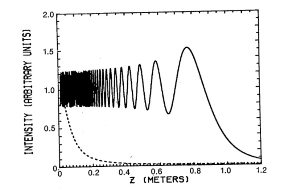
The history of the study of Bessel beams begins at the end of the last century. A non-diffracting beam-like field was first described by Durnin in 1987. In his study, Durnin describes such beams by saying that the amount of contained energy in each ring of the cross-section turns out to be approximately equal to the maximum energy at the beginning of the beam. In other words, the author is talking about the low-energy dissipation of a non-diffracting light beam, which requires infinite energy to create. It is noteworthy that Durnin does not call such a beam a Bessel beam but uses first-order Bessel functions to describe the transverse characteristics of the observed field. The image presented by Durnin shows the electromagnetic intensity distribution for a Bessel beam and a Gaussian beam (Figure 12). It can be clearly seen that at the minimum distance from the axicon lens, the Bessel beam, unlike the Gauss beam, has a comparably constant intensity: the wave amplitudes are almost identical. However, the intensity of the Bessel beam undergoes sharp fluctuations during the continuation of the removal, and the energy density ceases to become finite. Interestingly, the Bessel beam exhibits a sharp peak in intensity before it is completely attenuated.
The difference in diffraction capability and intensity capacity over time are the two main criteria creating differences between Gaussian and Bessel beams. Reference to Figure 13 shows that the Gaussian beam rigidly concentrates stored energy but quickly dissipates as a result of multiple diffractions in space. In contrast to the Gaussian beam, the Besselian beam is stationary in three-dimensional space because diffraction for this beam is not observed close to the axicon lens. Even from the dark regions shown in Figure 13, one can see that the Bessel beam has better resolving power and thus is able to produce sharper images for the objects being studied, unlike the Gaussian beam. However, the diffraction range of the Bessel beam is limited by the size of the initial lens, so infinite longitudinal energy accumulation cannot be achieved.
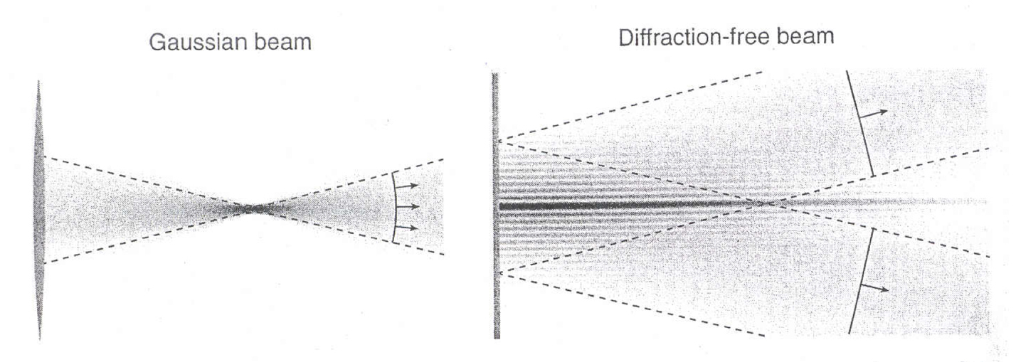
The transverse profile of the two beams differs as they move away from the axicon lens. More precisely, the function ω(z) determines the size of the beam width (“ray waist”) as a function of the distance on the Z-axis going along the optical axis of the axicon lens. For a Gaussian beam, ω(z) = ωG√1 + (z / zR)², which means that the radial waist of such a field effectively increases with distance from the lens. A typical scattering of the Gaussian beam due to multiple diffractions is observed. Another response to the forced beam expansion can also be found. Since the energy density decreases rapidly with distance from the lens, the Gaussian beam is forced to reduce its intensity in order to conserve energy. In contrast, for a Bessel beam, the width function will be invariant and constant; hence ω(z)=ωB, that is, for an ideal mathematical model, the intensity of the light beam does not change with distance from the axicon.
Among the advantages of Bessel beams is the fact that they do not undergo diffraction and therefore are able to maintain their focused intensity for an extended period. This can be used for unobstructed signal transmission without losses and noise. Meanwhile, Bessel beams have an exceptional depth of focus and are capable of self-restoration. All these advantages lead to the recognition of the industrial and scientific value of these beams so that they can be used in applications in medicine, acoustics, and nanotechnology. In particular, a clinical concept of optical coherence tomography was developed using Bessel emission, which allows obtaining images of critically small objects in situ with high accuracy using axicon lenses. In contrast to Bessel beams, Gauss beams cannot maintain such focal accuracy and therefore do not find such wide application in tomography. In addition, Bessel beams are used in optical nanotechnology to form Bragger diffraction gratings and microchannels, as well as for photopolymerization problems.
However, Bessel beams are not devoid of drawbacks, which hinder the possibilities of the most highly efficient use of this phenomenon. In particular, a large amount of energy must be applied to create non-diffracting beams, which means that the procedure of creating Bessel pseudo beams is energy-consuming. Regarding the feasibility of such costs, the question of the length of the Bessel beam before the final attenuation, that is, the capacitance is a natural one. In addition, the concentric focal rings of the Bessel beam form outgrowths over time, which degrade image quality. Thus, although Bessel pseudo beams are an excellent resource for modern optics, they are not without drawbacks.
Conclusion
The optical properties of light beams are extensive, presenting opportunities for applications. The diffraction of light beams, which results in a diffraction pattern, has been considered in this report. Light beams are a set of rays having a collinear co-direction. When a beam passes through an obstacle, according to the Fresnel-Huygens principle, sources of secondary spherical waves with coherence are created at the edges of the obstacle. The coherent waves interfere with each other and form a diffraction pattern on the screen. It was shown in the report that the nature of this picture depends on the number of slits in the obstacle and can be recursive. Differences between the two types of diffraction were also suggested, depending on the nature of which beams are subjected to diffraction.
In addition, this paper introduced the concept of Bessel beams, an ideal mathematical model of a beam in which an infinite amount of energy is contained. A Bessel beam does not diffract so that it can remain focused indefinitely. In practice, it is impossible to obtain such a beam because an unprecedented amount of energy must be applied to create it. However, the transmission of a Gaussian beam through an axicon lens makes it possible to obtain a Bessel pseudo beam, which confirms the properties of this model in a limited space. The differences between the Gaussian and Bessel beams have been given, and practical applications of these beams and the axicon lens have been shown.
References
Deen, A. N. (2022) Basic laws of optics. Web.
Geometrical optics (ray optics). (2020). Web.
Define light rays and beams. (2021). Web.
Geerts, E., & Van der Tuin, I. (2021). Almanac: Diffraction & reading diffractively. Matter: Journal of New Materialist Research, 2(1), 173-177.
Diffraction of light. (2019). Web.
Ling, S. J. (2021) The Huygens-Fresnel principle. Web.
Single-slit diffraction. (2021). Web.
Diffraction. (2020). Web.
Topuzoski, S. (2019). Fresnel and Fraunhofer diffraction of (l, n) th-mode Laguerre–Gaussian laser beam by a fork-shaped grating. Journal of Modern Optics, 66(14), 1514-1527.
Liu, H., Xue, H., Liu, Y., Feng, Q., & Li, L. (2020). Generation of high-order Bessel orbital angular momentum vortex beam using a single-layer reflective metasurface. IEEE Access, 8, 126504-126510.
Bessel beam generation. (2018). Web.
Gaussian beam propagation. (2020). Web.
An in-depth look at axicons. (2020). Web.
Axicons(2020). Web.
Zhai, Z., Cheng, Z., Lv, Q., & Wang, X. (2020). Tunable axicons generated by Spatial light modulator with high-level phase computer-generated holograms. Applied Sciences, 10(15), 5127-5133.
Akturk, S., Arnold, C. L., Prade, B., & Mysyrowicz, A. (2009). Generation of high quality tunable Bessel beams using a liquid-immersion axicon. Optics Communications, 282(16), 3206-3209.
Milne, G., Jeffries, G. D., & Chiu, D. T. (2008). Tunable generation of Bessel beams with a fluidic axicon. Applied Physics Letters, 92(26), 1-3.
Doshay, S., Sell, D., Yang, J., Yang, R., & Fan, J. A. (2018). High-performance axicon lenses based on high-contrast, multilayer gratings. APL Photonics, 3(1), 1-8.
Durnin, J. J. J. A. (1987). Exact solutions for nondiffracting beams. The scalar theory. JOSA, 4(4), 651-654.
Nowack, R. L. (2019). A tale of two beams: Gaussian beams and Bessel beams. Web.
Fuscaldo, W., Burghignoli, P., & Galli, A. (2021). A comparative analysis of Bessel and Gaussian beams beyond the paraxial approximation. Optik, 240, 1-12.
Khonina, S. N., Kazanskiy, N. L., Karpeev, S. V., & Butt, M. A. (2020). Bessel beam: Significance and applications—A progressive review. Micro Machines, 11(11), 997-1004.