Aims, Objectives and Deliverables
The aircraft parts are designed in such a manner that they carry much heavier loads than their material potency. They are likely to develop some flaws in course of time because of the cyclic stress experienced during landing, flying taxiing and pressurizing the cabin.
The aim of this paper is to analyze different Non-Destructive Methods of detecting these flaws within the aircraft structures. Moreover, it intends to evaluate different NDT methods on the basis of their applications, advantages and disadvantages, in aircraft manufacturing and in-service maintenance.
The NDT inspections will always hold a special place in the aeronautics as there will always be a need to carry out inspections in the manufacturing of new aircraft and maintenance of the aging ones to ensure their operational and in–service value. The NDT aims at detecting the flaws while they are within tolerable limits so that appropriate measures can be taken in time. This paper focuses on the role of NDT in reducing the cost of flying airplanes and their maintenance along with ensuring enhanced safety in flying.
Abstract
The vulnerability of the almost all equipment, particularly the mobile equipment, to damages, generates the requirement of some methods contributing to their safety and proper functioning. The components of aircraft suffer from high cyclic stress level causing cyclic fatigue or failure. So, a periodic in-service inspection of the vital components is obligatory. Non-Destructive Testing, generally known as NDT, is applied to test various materials and components used in the manufacturing of an aircraft as it provides accurate inspection without dismantling the aircraft in pieces. This paper focuses on the various NDT methods like: Eddy Current Method; Magnetic Particle Testing; X-Ray Methods; Ultrasonic Inspection Systems; Gamma Radiography; Dye Penetrate Inspections; and advances in Thermographic Methods.
The different NDT methods are discussed along with their principles, applications, advantages and disadvantages. The NDT methods for Composite materials and Shearography also hold a special position in providing safety measures in aerospace. There are certain standards set for the personnel working in this field. The requirement of personnel training, qualification and certification in carrying out NDT is made comprehensible.
Besides adequate qualification and training, there is always a need for the suitable software programs which assist in the efficient execution of the testing methods. The different NDT software programs and their utility relative to their specific testing methods are acknowledged in this paper. Computed Radiography system is recognized as an advancement in NDT methods as it provides digitalization of the images so that they can be stored in an electronic format. For the implementation of the advanced procedures in testing through different methods, it is essential to have NDT advanced equipment which are illustrated in this paper.
Having various advanced methods and techniques along with hi-tech software programs and ultra-modern equipment is not sufficient. These can be considered significant only when proven through some experimentation. So, here is a detailed interpretation of some NDT experiments. This dissertation may be useful in apprehending the importance of NDT for the aviation industry.
Literature Review
The experiments to verify the Fluorescence’s characteristic of Magnetic Particles was developed. The Durr CR 7 is a newly introduced desktop scanner which is ideal for critical inspections mainly with small imaging plates. The imaging plates used in CR are cost effective as these are reusable. The experiments to verify the Fluorescence’s characteristics of Magnetic Particles were developed. The internal defects in the structure of composite materials, after the excitation, are apparent by the use shearography.
It is essential that non-destructive testing of all vital parts of an aircraft is done at regular intervals. NDT is also applicable in components made from composite materials. Places like airports use gamma-radiography for detection as it is more penetrating because of the source like cobalt-60 that is moveable and simple. It is a flexible nondestructive method. Various measures are adopted by the manufacturers to avoid or reduce the risk of failure of these structures.
The use of NDT method and equipment is apt and effective for this purpose. Conventional radiology has done advancement in the form of digitalization of the images so that they can be stored in an electronic format. Along with other parts the turbine blade has to be inspected regularly. The newly developed eddy current technique uses a broadband plate repeatedly to excite the probe’s driving coil. It is a flexible nondestructive method but an expensive method. Different software programs are developed for NDT.
The training and certification of the personnel conducting the non-destructive tests is necessary as per the standards set by the industry. Magnetic flux is created with the help of magnetic particles to detect discontinuities. Ultrasonic method uses transducers for detection of defects. NDT provides minute inspection of all the parts of an aircraft. In designing and manufacturing process of a product NDI plays a very significant role.
Shearography is mainly useful in detecting the defects like disbands, delamination, wrinkles, porosity, foreign objects and impact damage. Thermal NDT is mainly used in establishing thermal differences and irregularities. Gamma-ray radiography has simple equipment, compact radioactive sources and no outside electrical source required in carrying out the inspection. There is a certain tolerance limit of materials used in the construction. Dye penetrant method is simple but applies many consumables. There is many reasons that lead to the malfunctioning of an aircraft cause hindrance in the proper functioning of the structure.
Methods of Non-Destructive Crack Detection in the Aviation Industry
Introduction
Almost all kinds of mobile equipment like aircraft, mining plants, vehicles, cranes etc. have highly stressed structures that are susceptible to fatigue failure. Not only mobile but fixed structures like offshore platforms, pressure plants and rotating plants may also experience fatigue failure (Wishaw n.d.).Aviation safety organizations are very much interested in the rotation of aircraft engines’ components for enhancing safety measures (Aziz et al 2005). There are many causes that lead to the malfunctioning and develop cracks in the structures of any kind of mobile equipment which eventually causes hindrance in the proper functioning of the structure. High cyclic stress level in the components is the major cause of cyclic fatigue or failure.
Moreover, lack of continuity at welds or addition of gases or impurities in the metal and the corrosive agents like water, oxygen and chemicals that are produced by the rubbing of surfaces make the condition adverse (Wishaw n.d.).According to Winshaw (n.d.), various measures are taken by the manufacturers of such plants to avoid or reduce the risk of failure. The in-service loads are estimated cautiously and computational finite-element models are developed.
Further, the quality of materials and scale models is also checked carefully as the correlation between the materials and the computational work depends mainly on the behavior of materials. It is important that the vital components of these assets should undergo periodic in-service inspections and adequate measures should be taken in case of those parts where replacement is required. The aviation industry has to be more cautious as there is a great need of such periodic inspections to deal with the problems related to safety. Therefore, there is an urge for technology such as Non-Destructive Testing generally known as NDT.
The various materials used in the manufacturing of an aircraft are prone to damages. It is not possible to dismantle the aircraft in pieces and then inspect each component. So, the NDT method and equipment selection is apt and effective (Khan 1999). Godbole & Gokhale (2006) state that periodic non-destructive inspections of the parts of aircrafts like wheel, turbine blades, aircraft lap splices are very important to avoid disasters.
Therefore, such inspections are made compulsory for aircrafts for past several years. As an aircraft becomes old it is natural to develop fatigue cracks in its structure and different components. The structural strength of the aircrafts gets frail. A major cause of this degradation is due to corrosion. To maintain the airworthiness of an aircraft it is essential to do the non-destructive testing of the vital parts like aluminum alloys, bolt hole inspection, wheels and lap splices etc. at regular intervals.
According to Tober & Shiller (2000) It is necessary for ensuring the production quality of components and maintaining their integrity thereafter that they should undergo proper inspection. The NDT plays a vital role in providing this quality. The specifically developed NDT inspection procedures also provide assured testing for the commercial aircrafts that require economic efficiency for a new attainment in their operations.
The NDT inspections in the aeronautic will always hold a special place in the aeronautics as there will always be a need to carry out inspections in the manufacturing of new aircrafts and maintenance of the aging ones to ensure their operational and in service value. The determination to achieve the best possible economic efficiency with optimal safe operational system has been the prime motivation factor in the advancement in the aviation industry. The aircrafts used for civil transportation are supposed to have optimum structural reliability. These are anticipated to have a long service life with appropriate performance demanding maintenance and repairs at long intervals.
So, the primary objective of the advanced NDT is to present an aircraft in its final form withal these characteristics (Tober & Shiller 2000).The prevailing conception of damage control involves use of new materials and constructions, utilization of the available material to the fullest and maximized dimensioning. Materials used in the construction determine the tolerance size of a damage or defect. The individual parts or the whole aircraft section has to undergo a fatigue strength test to determine the tolerable defect sizes in a particular material. If there is any defect that surpasses these tolerance limits must be inspected by the NDT methods.
The low steam turbine failure is usually due to the fatigue caused by vibration. These failures are in the form of micro-cracks. The detection of these cracks is important to avoid any injuries and damage to the machinery. So, for assessing the robustness of the turbine blade it is important that periodic inspection with NDT is carried out (Kotambkar 2010).During the renovation process, crack is introduced in the blade of turbine accidentally. Therefore the requirement for methods with added global damage detection has paved the way for the development and continued research in this field.
Eddy Current Testing (ECT)
Wishaw (n.d.) mentions that the Eddy Current Testing is based on the principle of induction. Eddy Currents can be produced in the surface of an object by generating high current in a coil and keeping it close to the metal to be tested.
Aerospace Eddy Current Applications
Detection of surface cracks on aluminum alloys: “For inspecting the cracks in the surface of aircraft structures eddy current pencil probes are used. Aircraft structures are either flat or slightly curved so these eddy current pencil probes are apt for their inspection. This instrument requires a standard block of aluminum alloy with EDM notches of 0.5mm and 1.0mm depth for calibration. The phase is regulated in such a manner that the lift-off signal goes to the left of screen horizontally.
So, information about the defect can be easily obtained by looking at the y-component of the signal in spite of the unavoidable staggering and clumsy motion of the investigation” (Godbole & Gokhale 2006, p. 320). “TECHNOFOUR SD-PC-12 Eddy Current Instrument is quite useful in regulating lift-off horizontally because of its suitable “Auto lift-off” element. The size and center of the alarm box can be changed according to our need. The alarm is systematized in such a way that while the signals are inside or go outside the box the alarms go off” (Godbole & Gokhale 2006, p. 320).
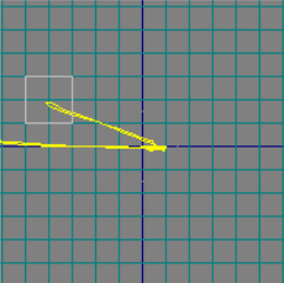
“A crack in 10mm drill hole of aluminum block has a distinctive response when it is tested with Technofour’s Eddy Current Tester SD-PC-12” (Godbole & Gokhale 2006, p.320).
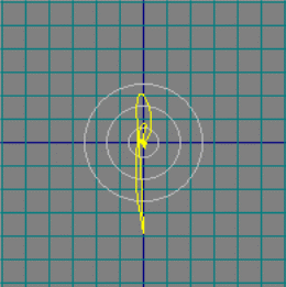
Bolt hole inspection
“The discontinuities in the inner surface of the holes in a component are so minute that cannot be detected with clasps or hardware installed in the holes a special bolt-hole probe is used for detecting the defects. This inspection requires a hand held rotary scanner. A block of a similar metal having right hole sizes representing the variety of holes to be inspected is used for standard calibration. The calibration consists of 0.5mm deep and 0.12mm wide EDM notch in each hole.
The Eddy Current instrument is positioned for dynamic testing while using the hand held rotary scanner. Only those probes which scan a defect at a certain speed will be allowed to pass through the high pass filters present in the Dynamic mode of testing. So, typical quick excursions from the origin can be noticed as the ‘flying-spot’ of the xy-display stay at the center” (Godbole & Gokhale 2006, p. 321).
Automated Inspection of Aircraft Wheels / Wheel Hub / Rotor Disc
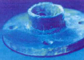
“The wheels of an aircraft carry out quite challenging tasks. There is a lot of repetitive stress passed on to the wheels in the landing and breaking process of the aircraft. This can lead to damage and eventually grow into cracks. These cracks may result in deflation or breaking of wheels on landing. So, there is a great need for periodic Eddy Current Inspection for detection of cracks on wheels. Usually a tire needs replacement after 300 landings.
So, while replacing the tire the Eddy Current Inspection should be conducted to detect any kind of minute defect that may take a dangerous size in the next 300 landings. For I Stage Disc checking artificial notch of 0.5mm depth x0.12mm width is made on the disc and is checked by TECNOFOUR SD-PC-12 FOR calibration. Frequency can be used as per requirement” (Godbole & Gokhale 2006, p. 321).
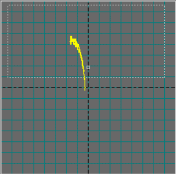
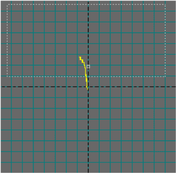
This calibration provides the manual scanning of defects in I Stage Disc
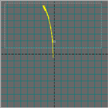
In case of overheating of the wheel some additional inspections are also required to check the conductivity and hardness.
Subsurface Corrosion Detection
“Though there is a great care taken at the time of designing the primary flight loaded structures of airplanes to make them fail safe but corrosion may affect their fatigue performance. The lap splices are vulnerable to corrosion as they are bonded and riveted. This necessitates the need for inspections at regular intervals so that any defect in them can be detected timely to avoid any damage. Any sign of corrosion detected visually is to be verified by Eddy Current Inspection.
The best possible operating frequency is used on the basis of the thickness of lap splices that has two layers between 0.8mm to3.2mm rivate. A material having similar kind of thickness and conductivity is selected as a reference standard that reproduces the material loss due to corrosion in a certain percentage of reduction in the thickness” (Godbole & Gokhale 2006, p. 322).
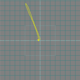
“With the use of TECHNOFOUR SD-PC-12 Eddy Current instrument and a send receive probe at 5KHz the defects were detected flawlessly” (Godbole & Gokhale 2006, p. 322).
Surface Inspection with Array Probe
The surface inspection used to be implemented with the help of pancake surface probe which had many flaws as it was conducted manually and varied from person to person (Godbole & Gokhale 2006). In the Array Probe Inspection several coils are positioned in such a manner that a single scan can cover a vast area at a time. The dead zone between the two elements is filled with another adjoining array which is tilted by half an element.

To manage the needed switching and multiplexing a micro- miniature circuitry is incorporated in the probe itself. “In the figures below Transverse defects and longitudinal defects are scanned where the signals are demonstrated by artificial defects” (Godbole & Gokhale 2006, p. 324).

“The signals are coded by colors. Hot colors like yellow-orange-red represent the positive signals and cool colors like blue, and black are for negative signals whereas signals near zero are represented by green (Godbole & Gokhale 2006).
Aircraft inspection has become convenient, trustworthy and repeatable with the modern techniques and inspection equipment like SD-PC-12” (Godbole & Gokhale 2006, p. 324).
Pulsed Eddy Current Method
“This newly developed eddy current technique incorporates a broadband plate repeatedly to excite the probe’s driving coil. The momentary currents which generate through the coils are induced in the test piece combined with much calmed magnetic pulses circulating through the material” (Lepine et al 1999, Para 1).
Lepine et al (1999) mentions that with the detection of decay of the induced field a series of voltage-time data are generated at every search location which is corresponding to the ultrasonic inspection data. This method offers a facility to adjust the excitation pulse, sensor and signal gain patterns according to the specific applications.
Advantages of Eddy Current Testing
The Eddy Current Testing is useful in many ways for almost all kind of automation. The quality of material can be tested on various conditions affirming its strength. An extensive range of engineering metals can be tested on ground of composition, hardness of the metal, conductivity and porosity (Willcox & Downes 2003).The units used in Eddy Current Inspection testing are quite compact and can be moved from one place to another.
In this kind of inspection the information is usually offered only in terms like: go/no go. For vast information on the product phase display units can be used. Eddy Current Testing allows the use of different probes and test frequencies according to the requirement. The inspection unit is sturdy and long lasting except the probes which may need to repaired in course of time.
Disadvantages of Eddy Current Testing
Eddy Current reactions may be affected by certain limitations such as signals from a crack in a material could be camouflaged by some unwanted parameter as the change in the hardness of the material. Another drawback in this testing is that it is mainly confined to surface breaking or to some extent flaws in the subsurface.
Magnetic Particle Inspection
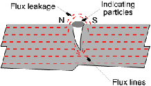
In Magnetic Particle Inspection a component made from ferromagnetic material is used to create a magnetic field where the lines of force travel exiting and reentering the material at the poles. In the presence of a crack or void some flux is forced outside of the part which attracts the magnetic particles spread over the component and can be visualized (NDT Method Summary n.d.).
Willcox & Downes (2003) state that the principle behind this testing is to produce magnetic fluctuation in the component to be inspected. The flux lines stray out in the air at the opening of a crack. The edge of the crack is attracted to the magnetic poles North and South which are capable of attracting particles of magnetic materials. The particles are mostly suspended in a liquid to enable them to move easily on the surface towards the crack edges. These particles are red or black or coated with a fluorescent substance so that the cracks should be visible in presence of the ultra-violet lighting. The Magnetic Particle Inspection helps in detecting defects that cannot be observed with naked eyes.
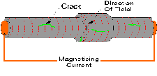
Though magnetic flux can be generated in the test piece by applying a permanent magnetic to the surface but electrically produced magnetic fields by modern equipments are more accurately controlled. These can be produced directly or indirectly. In the direct method magnetic flux is produced by passing a high amperage current through the subject towards the expected defect. The indirect method is used when the direction of the defect does not allow the direct method to perform. The indirect method can be used in two ways. One is to encircle the area to be tested by a coil and pass a high current through the coil.
For detecting the transverse and circumferential defects a piece of yoke that is coiled with current is used to pass the magnetic fluctuation (Willcox & Downes 2003).The threading bar technique can be used for testing subjects where cracks spread out from holes. In this case a conductor carrying current is passed through the hole. One example of this technique is the detection of longitudinal defects in hollow shafts.
“The magnetic flux can be generated by alternating current, half wave rectified direct current. The magnetic flux produced by A.C. mainly goes to the outlines of the surface while H.W.D.C. enters a little deep and is useful for detecting defects in the subsurface. Penetration with D.C. can be deeper but demagnetizing after D.C. magnetizing is not trouble-free as compared to A.C. magnetizing. The newly emerged Swinging Field Method of multi –directional magnetizing has made it easier to detect all defects with a single magnetizing shot” (Willcox & Downes 2003, p. 8).This has resolved the problem of magnetizing the test piece in two directions and made the process quick as compared to the traditional magnetizing tests.
“Magnetic Particle Crack detection equipments are of two types depending on the requirement. The first type of equipment is used for huge and immovable test pieces. It works as a power pack that produces a high current and sends it to the subject by surrounding coil of cable. A maximum of 2000Amps for portable units and 10,000Amps for mobile equipments of both A.C. and H.W.D.C. magnetizing current can be used by this equipment. A spray is used on the representing material in this type of equipment” (Willcox & Downes 2003, p.8).
“A bench type of equipment is used for smaller and handy test pieces. The power pack is same as in the first equipment. This equipment uses indicating ink system that circulates around the already circulating fluid to get hold of the testing piece firmly so that the magnetic flux can be applied in a systematic and controlled manner. This kind of equipment is perfect for investigative work or routine quality control checking.
To obtain the best results ultra-violet fluorescent material is used and direct light is blocked by the use of a canopy. The indicating material can either be suspended in water or very thin oil or can be applied dry. The defect signals can be checked visually but certain extent of loading, inking, magnetizing and unloading can be automated” (Willcox & Downes 2003, p.10).
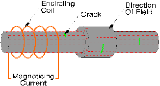
Advantages of Magnetic Particle Crack Detection
The Magnetic Particle Crack Detection method is very convenient and uncomplicated. It is quantitative and can be automated also. In NDT Method Summary (n.d) it is said that with this testing a quick inspection of the large surface areas of a complex part can be done. The surface or subsurface defects can be detected and the surface preparation is hassle free. We can have the image of any discontinuity on the surface of the component as magnetic particles signs are generated directly on the surface. The equipment is less expensive than those used in the other methods.
Disadvantages of Magnetic Particle Crack Detection
NDT Method Summary (n.d) further mentions that the limitations of this method are that it can be applied to the ferromagnetic materials only. It can detect the defects of surface or close to surface area. In absence of indications there may be misunderstanding as it could suggest two things i.e. there are no defects detected or the testing process is not incorporated appropriately. It is difficult to arrange the magnetic field and defect properly. Parts that are huge in size require large currents. The effectiveness of the testing is influenced by the non-magnetic materials or paint etc. It requires proper cleaning and demagnetizing of the magnetized part.
Advances in Thermo graphic methods: Snell & Spring (2007) believe that the Infrared Thermography is applied to measure variations in heat released by an object which eventually is changed into visible images. This non –destructive technology is frequently used and new advances in the imaging equipment have rendered it more potential in acquiring rapid data and better spatial resolutions. Thermal NDT is mainly used in establishing thermal differences and irregularities.
In the new advanced technique we can get data in the form of digital, electronic files. This data that is in the form of an image is stored for later comparisons and documenting flaws for maintenance service.In the past decades the use of thermography has increased extensively in the aerospace industry. The frequent uses of more composite materials require supervision of their quality and maintenance.
The principle behind the Aerospace composite thermography is that if a material is properly bonded or laminated it will have reasonably uniform and recognized thermal traits such as conductivity, capacitance and diffusivity. The irregularities and defects like disbonding or delamination are indicated by abnormal thermal signs.
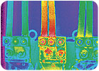
Snell & Spring (2007) state for this type of testing the testing piece is heated from one side and viewed from either the same side or the other side. The heat has to be applied evenly using hot air guns, heat lamps or flash lamps which allow the heat to in single direction through the material perpendicular to the surface. The thermal diffusivity of a material determines the movement of heat energy from the heated surface into the cooler part in case of a thermal inclination within the component. The relation of the thermal conductivity with its thermal capacitance is known as thermal diffusivity. If a component is in thermal equilibrium with its environment, the applied heat flow is unidirectional, from the front surface to the back surface diffusing heat throughout the material unless or until any discontinuity obstructs its flow.
The thermal properties of a defective material are different than that of the base material in the composite structure. A lower rate of thermal conductivity is found in case of delamination, disbonds or void which leads to the trapping of heat over the discontinuity. This build-up heat makes the particular surface warmer. The location and approximate size of the discontinuity can be traced with this method. If there is any water or fluid access into the composite structure the surface over that particular area gets cooler after the heat being applied to it. Different specific techniques are used in aerospace components to detect the subsurface defects.
The heat energy is transmitted in different ways into the component in different methods like passive, active, active-pulse thermography and vibrothermography. The method to be used has to be suitable to the particular inspection. The thermal quality of the part to be inspected, flaw types, their sizes and direction is to be considered. Besides this the method of inducing heat to the component also matters. The sensitivity and spatial resolution of the infrared imager has to be in harmony with the inspection.
Vibrothermography
According to Snell & Spring (2007) in this method ultrasonic waves are stimulated into the component which produces vibrations within the crack causing frictional heating. This method was first used in 1980s and new development in high-speed data capture has given it more popularity.
Passive Thermography: Snell & Spring (2007) mention that the passive thermography is applied to the subject during or after the thermal operational cycle. The manufacturing process or normal operation of the aerospace component involves the thermal cycle. For instance, inspection of an aircraft just after its landing from a high altitude for checking water ingression. The thermal inspection in this situation is possible as the water would remain cooler than the surface material for some time due to its high thermal capacitance. Components that go through a thermal process like autoclave curing can be tested just after the thermal cycle. Thermal imaging systems are very useful in the inspecting the of laminate and composite material.
It is essential that the person inspecting the test must be at the right place at the right time in Passive Thermography. Preferably it should be incorporated in a manufacturing situation where an automated thermal system is available. The momentary thermal incidences like the landing aircraft could be difficult to handle. Moreover, conflicting conclusions could be drawn since a component may go through different thermal cycle each time.
The distinctive feature of Passive thermography is that it works without taking the aircraft out of service and a large area of the aircraft can be inspected promptly (Snell & Spring 2007).Active Thermography: Active Thermography uses a thermographer to induce a thermal gradient into the component by purposely heating or cooling the surface of the component. Sources of heat can be hot air guns, quartz lamps and even the sun (Snell & Spring 2007).It is more effective as the thermal cycle can be controlled by the thermographer.
The intensity and duration of the thermal cycle can be coordinated with the thermal characteristics of the component to be inspected. The initiation of the thermal cycle can be controlled by the thermographer. This method is useful for those materials that are slow in thermal conducting. Constant thermal flaws can be detected aptly by this method. Consistent amount of heat is required during each testing for repeatable results. Thermally slow materials with deep or thermally consistent flaws are inspected more appropriately than thin or thermally fast materials (Snell & Spring 2007).
Pulse Active Thermography: “In the Pulse Active Thermology the flash lamps release light and the pulse of light energy is absorbed by surface of the component. A number of images are captured at rates up to 500 frames per second with the diffusion of heat into the component. With the help of strong software analysis and trained and expert operators flaws can be detected in the materials that are thin and highly conductive. This method is appropriate for detecting flaws in momentary thermal events. The procedure takes only a few seconds and an area of about 3 sq.ft.is inspected in one go. This method involves uniform heat input and the speed in which the images are captured is very high delivering extremely repeatable results” (Snell & Spring 2007, Para 19).However, this method, like any other NDT method needs to be verified in the inspection of critical components. The pulse active thermography is consented to be applied in the Boeing and Airbus for NDT inspection (Snell & Spring 2007).
In the past few years a process of “reconstructing” the computer image data taken from the infrared camera into a mathematical representation which describes the sequential response of each detector element of the IR camera array has been practiced. This is called Thermographic Signal Reconstruction (TCR) (Snell & Spring 2007).
TSR has become very effective in real-world manufacturing and in-service inspection with the quality of combining together the sequential images of a component. The flaws can be seen in the best thermal contrast in the whole component. The size and depth of the defects can be measured automatically and this has proven to be a great advantage for active thermography. Along with the active and passive methods of thermology that are being applied to the appropriate materials the automated thermal NDT systems have a great future as repeatable inspections can be performed with them (Snell & Spring 2007).
Advantages: According to Maldague (n.d.) active thermology is a flexible nondestructive method that can be used in variety of situations and materials. It performs the inspection in seconds. This method is does not require any contact or inducement to the object to be tested. It can be applied to both curved and flat surface. Critical objects that have only one side entry can be inspected through thermography. So, it saves the time and resources by carrying out the inspection of the part in service (Ingold n.d.).It is a safe method as harmful radiations are not used. The findings are in the form of images so are easy to understand.
Disadvantages: According to Maldague (n.d.) like any other thermology too have some limitations. A limited thickness of a material which is under the surface can be inspected (Maldague n.d.).Applying a lot of energy uniformly over a large surface in seconds is difficult. The equipment like IR camera, thermal stimulation units for active thermography are very expensive.
Ultrasonic Flaw Detection
The Ultrasonic Inspection Systems are applied in the detection of the internal (Maintenance and Repairs: Crack Detection n.d.) and surface defects on the materials that are sound conducting (Willcox & Downes 2003). In this inspection transducers are used to propagate sound waves into a material. The detection of flaws is determined by the analysis of the amount of energy transmitted or received and the time used in receiving the energy (NDT Method Summary n.d.).
Since the 1940’s the ultrasonic testing techniques based on the laws of Physics are popular in detecting hidden cracks, gaps or other permeability and certain other flaws in metals, ceramics, plastics and composites. The circulation of sound waves through material is useful in detecting defects in the internal and surface level. In case of any flaw the high frequency sound waves echo in an expected manner. Portable instruments can display and record these echo patterns. Being a non –destructive and safe method it is used in manufacturing, process and service industries engaged mainly with welds and structural metal (Nelligan 2011).
The Ultrasonic Inspection system is based on the theory of Physics. The organized mechanical vibrations travelling through a medium are known as sound waves. These waves travel through a medium such as a solid liquid or gas in an expected direction and at a definite speed or velocity. These waves will be returned or put out when they come across some boundary with different medium. There are many types of ultrasonic transducers that are used In flaw detection, such as contact transducers, Angle Beam Transducers, Delay line Transducers, Immersion Transducers and Dual Element Transducers. For detecting permeability, voids, cracks or delamination alongside the outside surface of a component, It is also useful in measuring thickness. The contact transducers are used to introduce sound energy directly at right angles to the surface of the test piece. Angle Beam Transducers are used in the inspection of welds. This transducer performs the task of introducing shear waves or longitudinal waves into a test piece at a selected angle with reference to the surface in combination with plastic or angle beams.
Another type of transducers are the Delay Line Transducers are used in high temperature testing to check the thermal damage by applying a short plastic waveguide between the test piece and the element. Dual Element Transducers can work at high temperature. These types of transducers are used in the inspection of rough surface, crude crumbed material and testing pitting or permeability (Nelligan 2011).Ultrasonic flaw detection works on the grounds of comparison. A trained operator compares the echo patterns from the good parts and from the representative flaws by using suitable reference standards and commonly used test patterns.
Straight Beam Testing
Nelligan (2011) mentions that this testing is normally used in detecting permeability and voids as well as cracks and delamination alongside the surface of the test piece. For this purpose delay line transducers, contact transducers, dual element or immersion transducers can be used. This testing works on the theory that sound energy keeps travelling or propagating through a medium unless it is broken up or reflected off a boundary with some other material for example the air surrounding a far wall or crack found inside. The transducer is attached to the test piece to trace the echo that returns from the far wall of the piece which is tested. If there is any crack or void detected, a noteworthy echo is heard preceding the back wall echo.

Nelligan (2011) further says that for testing some specific cases a through transmission mode where two transducers are attached on both sides of the test piece. The sound energy traveling between these two transducers is blocked by the beam and no sound pulse is received if there is any defect in the sound path.
Angle Beam Testing
Typical Angle Beam Testing is applied where the cracks or other discontinuities are not visible with the straight beam techniques as they are tilted or perpendicular to the surface. This type of testing is commonly used in detecting defects in welds, structural parts of metal and some other important components. To direct sound energy into the test piece either common angle beam transducer assemblies or immersion transducers aligned are incorporated (Nelligan 2011).
Mode conversion and Snell’s law is used to produce shear wave at a desired angle in the test piece. The increase in the conversion of sound energy to shear waves is determined by the increase of the angle of an incident longitudinal wave from the surface. Cracks perpendicular to the far surface of the test piece and perpendicular to the coupling surface after rebounding are easily detectable with the use of the angled sound beam.
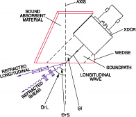

Typical Angle Beam Assembly
Advantages
In NDT Method Summary (n.d) it is said that Ultrasonic Flaw Testing provides a deeper penetration for detecting the flaws or measurement than other methods.So; it can be useful in the inspection of cracks or voids that are perpendicular or tilted from the surface. It needs only one sided way in testing a component. It does not require much preparation for carrying out the procedure. It is helpful in providing distance information and can be used in many other areas except flaw detection.
Disadvantages: In NDT Method Summary (n.d) it is said that there are some limitations to this technique. First of all it requires an extensive training and expertise than the other methods. The probe used for testing should be easily entered to the surface. There may occur a problem with the surfaces which are not properly finished and rough. Not useful for the inspection of the thin parts of a structure and linear flaws can go undetected if they are leaning parallel to the sound beam. In almost every testing there is a reference standard required.
Dye Penetrant Testing
Penetrant inspection procedures are comparatively simple in their functioning. These provide reliable testing of nonporous metallic or nonmetallic materials for defects like corrosion, cracks, pits, etc. (Standard Practices and Structures 2011).
In NDT Method Summary (2011) it is further mentioned that this method is mainly applied to detect the flaws like cracks. permeability etc. in the surface of a material. The defects should be suitable for trapping and holding the penetrant dye for a short period of time. This method is suitable for most nonporous materials. The inspection of large areas can be done proficiently with this method.
Advantages: The Penetrate Testing is quite beneficial for the inspection of large surface ares. The process is fast and can be carried out with minimal expense. The visual image of any crack or discontinuity can be seen directly on the surface. Very few equipment are required for carrying out the inspection. It is ideal for inspecting parts with intricate geometry on a regular basis. The characteristic of Dye Penetrant Testing is that it is very simple to be conducted. This method can be applied automatically, though with some limitations. It provides quantitative results (Willcox & Downes 2003).
Disadvantages: The limitations of this technique lie in the fact that it can be applied only to the defects related to breaks in the surface. Besides this it requires a number of consumables. The lack of accurate response due to contaminants is another drawback with this type of testing (Willcox & Downes 2003).The surface has to be smooth and nonpermeable and the use of chemicals can be hazardous so great care is need regarding fire, toxity and waste.
X-Ray Method
Aviation and aerospace would have been unimaginable without the application of strong non-destructive testing (Wallenwein 1997).The x-ray technique is appropriate in the non –destructive testing of components having internal flaws. A radiation is penetrated into the material which in turn is absorbed by the material when the radiation passes through it. The intensity of absorption of the radiation depends on the thickness and density of the material.
The material to be tested is placed between the radiation source and the film. The defective ares are shown as darkened as more radiation reaches to film due to internal voids (Willcox & Downes 2003).The number of volts applied to in the X-Ray tube determines the penetrating intensity in X-radiography. Steel requires about 1000 volts per inch thickness for this purpose. The amperage of the cathode in the tube determines the intensity and the exposure time which is denoted in milli ampere minutes. The X radiograph is generated with the help of film and intensifying screens which are enclosed in a light tight cassette. This package is kept near the surface of the component to be tested.The radiation is passed from the source placed near the other side of the subject. It passes through the subject and then on to the film. The film is removed after the completion of this process. It can be viewed for analysis only after being processed and dried. A special viewer with transmitted light is used for viewing this film. The X-ray radiography requires many radiographic and photographic accessories for conducting the inspection. These include radiation monitors, film makers, image quality indicators, darkroom equipments along with the fragile items such as radiographic films and processing chemicals.
Gamma-radiography
Gamma-radiography is applied to test invisible cracks, defects and obstructions in a component. It is a non contact and non induced method of inspection as the material can be tested without direct contact and inducement. It is possible to carry out the inspection even if the material is in a mobile position such as convoy or belt (Industry: Gamma- Radiography n.d.).
In Industry: Gamma- Radiography (n.d.) it is said that the process is quick and does not demands much expensive. In the places like airports gamma-radiography is used for detection as it is more penetrating because of the source like cobalt-60 that is moveable and simple. The gamma rays are produced with a small pellet of radioactive material that is sealed in a titanium capsule. For screening of an object the capsule is placed on one side and on the other side a photographic film is placed where an image is created on passing of the gamma rays through the object.
“In the maintenance during gamma-radiography Iridium- 192 is usually used in the aircrafts. Gamma-ray radiography has simple equipment, compact radioactive sources and no outside electrical source required in carrying out the inspection” (Khan 1999, Para 5).
Gamma ray radiography is usually used where there is difficulty in accessibility to the part to be tested. It is used for detection of internal flaws of aircraft structure such as steel & titanium. Components such as the engine which require higher energy levels are also inspected with the help of this technique (Khan 1999).
Disadvantages: “Radiation hazard, aircraft must be clean of all personnel. Trained operator, film processing & viewing equipments required. Crack point must be nearly paralleled to X-ray beam. Eliminates many disassembly requirements provides permanent records of findings. Accessibility required in both sides of the test specimen” (Khan 1999, Para 6).
Non –Destructive Testing for Composite Material within Aviation Industry
Non-Destructive testing methods are beneficial for the many civilian as well as aviation industry and military areas as these help in detecting cracks or damages in materials and assessing their properties These testing methods provide guarantee for the good quality of the products, devices and construction. The non-destructive testing can be done on different kinds of joints of materials such as welded, soldered and glue joints. It is also applicable in components made from composite materials (Swiderski n.d.).Composite materials are recommended in various applications because of these are low in weight, corrosion free from corrosion and strong and steady. Composite materials have different structures and are susceptible to more serious damage than metal. So, these require specific kind of methods and techniques for inspection. The infrared thermography non –destructive testing methods are apt for composite constructions (Swiderski n.d.).
In the aviation industry it becomes essential to have a fool proof testing technique to avoid any kind of damage to the structures. These cellular filling structures may experience water penetration due to gaps and or lack of tightness at the superficial level. The safety of the flight is affected by freezing of water at high altitudes and due to differences in temperatures and pressures which cause splitting of the laminated cover from the cellular filling material. Water can get access inside the composite structure through even minute gaps of the composite material and this moisture can cause serious defect in it. These defects cannot be detected by normal non-destructive testing. So, it is essential to have a fast detection of micro-defects such as water and sogginess with the help of IR thermography non –destructive testing methods (Swiderski n.d.).
The nondestructive testing by IR thermography aims at testing the properties of an object when it is introduced to cyclic or impulse thermal stimulation like heating or cooling. The short-term processes that take place during this testing evaluate the quality of the object. The IR thermography does not contact or disturb the thermal patterns on the surface of objects. The differences between the non defective area and defective area in the thermal properties determine the detection of defects in IR thermography.
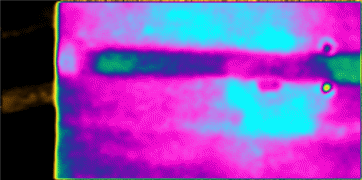
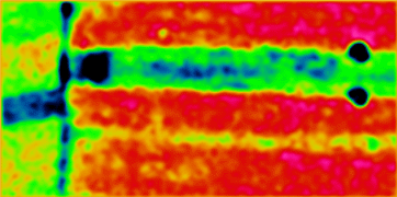
In Shearography: Non Destructive Testing (NDT) (2008) it is mentioned that Shearography is another non-destructive testing method that is largely used in the aviation industry. It is an optical testing method which is full-field and does not require any contact with the subject. It is mainly used in Quality inspection of the composites and other materials. The high rate of coverage i.e. ~1 m2/ minute makes it distinctive. Shearography is mainly useful in detecting the defects like disbands, delamination, wrinkles, porosity, foreign objects and impact damage.
It is a laser based interferometric technique that is responsive to the deformities in the outer surface of a plane. A laser, a digital camera, the shearing optics and an image acquisition hardware are normally used in shearography (Shreagraphy n.d.).This is an effective tool for the in-site environment. The application of this NDT technique has a wide-spread field such as in, aerospace, aeronautics, missiles, pressure vessels, marine etc. Shreagraphy can be applied to varied kind of structural defects irrespective of their material type such as a polymer, an elastomer, a composite or a metal. An effective inspection of disboundings, delamination, cracks, water ingression, overheating etc. can be carried out by this testing method.
Ferreira et al (2011) say that the internal defects in the structure of composite materials, after the excitation, are apparent by the use shearography. The irregularities in the interference fringes patterns are the indication of defects.
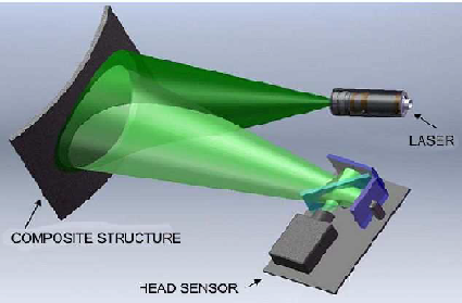
Advantages: Shrearograhy is a non-contact technique so quite useful for NDT. It is a global method that allows the inspection of a large surface up to 50×50 cm2 in a single shot. It is a high resolution system. Shrearography is useful as an interferometric method as it can be applied outside the laboratory environment (Shrearography n.d.).
Personnel Training, Qualification and Certification
Qualification of an individual includes his education work experience and training standard and good vision. The training and certification of the personnel conducting the non-destructive tests is necessary as per the standards set by the industry. Most of the NDT methods provide conclusions on the basis of individual observation of the personnel performing the test so they need to have a lot of confidence in the application of their knowledge and skills (NDT Certification 2010). A personnel needs to have many qualifications to perform efficiently in his field such as:
- Training to acquire knowledge with respect to his work,
- To gain experience in the desired field working under personnel who have already working in the same field for a period of time
- Now, passing an examination to prove that competence has been acquired in the desired field.
- Lastly, acquiring a certificate proving their competency.
The personnel can acquire certification in various NDT methods (NDT Certification 2010).
- Acoustic Emission Testing AE
- Electromagnetic Testing ET
- Leak Testing LT
- Liquid Penetrant Testing PT
- Magnetic Particle Testing MT
- Neutron Radiographic Testing NRT
- Radiographic Testing RT
- Thermal/Infrared Testing TIR
- Ultrasonic Testing UT
- Vibration Analysis Testing VA
- Visual Testing VT
Within each NDT method there are different levels of competence that are certified as Level I Limited, Level I, Level II, and Level III (NDT Certification 2010).
Level I certification allows the technicians to perform only certain kind of testing on certain set of components. It is not a trainee level but does not allow much liberty to the personnel in selection of the method or procedure for inspection. Their work is supervised by higher level personnel (NDT Certification 2010). The technicians possessing Level II certification have the right to set up and calibrate equipments. They can carry out the inspection as per the procedures, present the interpret ion and can do the documentation of the findings. They also work as trainers or supervisors for the Level I and Level I Limited technicians (NDT Certification 2010).Colleges and some other vocational schools these give NDT training to fulfill these requirements:
- Graduation from a university or college in engineering or science and one year experience of the standard of Level II in the desired NDT method.
- Two years of study in science or engineering at a university, or technical college along with two years experience in the desired method meeting the standards of Level II.
- A person having four years of experience meeting the standards of Level II is also eligible for NDT training.
Certification Examinations
A certification examination must be taken after the requirements related to education, training and work experience are met and filed. The process of examination includes a number of exams (NDT Certification 2010).After clearing the respective exams technicians are provided a nationally recognized central certification.
Visual Examination
An eye test is required to insure visual sharpness and color apparition of the NDT personnel. A person should be able to read a Jaeger Number 1 (or equivalent) type and size letter at 12 inches (for one eye).It is also required that one should be able to distinguish color contrast and shades of grey (NDT Certification 2010).
NDT Software
Rhythm Radiography (X-ray): This software NDT includes, tools for reviewing and managing data for all X-ray testing methods and acquiring advanced images It is used in computed radiography, digital radiography and digitization of film. It is capable of sharing advanced data which is helpful in improving the productivity considerably. The quality related problems can be identified rapidly. Therefore, is helpful in reducing the production defects and improving in-service management (Measurement and Control 2012).
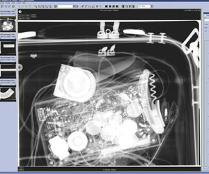
Rhythm Visual Software: For Remote Visual Inspection the Rhythm Visual software is developed. It involves superior image acquisition along with tools for reviewing and managing the data. Its data sharing capacity is highly developed which enables it to identify quality problems quickly and be helpful in improving the productivity. Thus lessening the production defects and improving the in-service management (Measurement and Control 2012).
Rhythm UT Software: The Rhythm UT software is used for achieving superior images. It also includes review and data management equipments. The phased array images are taken with the Phasor XS ultrasonic flaw detector. It provides high-quality production and in-service upgrading (Measurement and Control 2012).
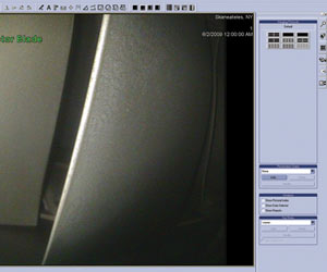
Rhythm UT helps in better decision-making by offering supplementary tools to boost reporting and analysis (Measurement and Control 2012).
Rhythm Enterprise Archive (Rhythm EA): It provides a complete and flexible DICONDE software for rapid, well-organized and consistent storage solution for NDT images and information. It can perform multifaceted tasks for robust on-site, multi-site, and off-site functioning. The disk space can be minimized with multiple compression techniques delivered by this software (Measurement and Control 2012).Besides this, it can Rhythm Enterprise Web: This software works in combination with Rhythm Enterprise Archive. It enables us to get access to NDT inspection data which is preserved in a central Rhythm Enterprise Archive server. With the use of a web browser and login information this information can be accessed conveniently. A web-based functionality with a convenient distribution engine is also offered by the software.
Ultra DOC: “This ultrasonic flaw detection analysis software is developed to make the transfer, storage and printing of the data and reports of the USN 60 and usn 58R more convenient and hassle free. It is quite simple to generate reports to Microsoft Word, Excel, or in HTML format” (Measurement and Control 2012, Para 6).
Ultra LOG 2.2.0: “This software is designed to work in combination with the USLT 2000 Ultrasonic flaw detection system. It is a special spot weld testing application. The results obtained from the inspections of the spot welds which are ultrasonically tested are stored and evaluated with the help of this document results from destructive, non-destructive and various other inspection methods” (Measurement and Control 2012, Para 7).
Data Base Manager: This software works as an option for the Ultra LOG 2.2.0. There is a facility to create multi-level, wide ranging inspection plans and circulate to many locations. In addition to this stationary or mobile systems can also be incorporated in a network with this system (Measurement and Control 2012).
Ultra WORKS: “Simple and easy programming of individual applications for the Ultrasonic Notebook USLT 2000 using Windows is provided by this ultrasonic development system. The person involved in the programming must have adequate knowledge about it. An ultrasonic plug-in card in the USLT 2000 matching with the OLE control modules (OCX) is used for bi-directional data exchange.This provides the accessibility to all adjustment parameters, A-scans, measurement data for the ultrasonic gates or status information for the ultrasonic unit” (Measurement and Control 2012, Para 10).
Ultra MATE: “This software has made the process of the transfer, storage, analysis, and documentation of thickness data much simpler. The convenient tool has direct DMS2 and CL 400 Communications along with “Auto-connects”. There is a facility to display and print color Readings reports” (Measurement and Control 2012, Para 11).
Ultra CAR: The results collected from different inspection locations, that have occurred over a certain period of time, are connected to the central database system. These results are now collected and evaluated with the help of this program. We can present the ultimate data graphically (Measurement and Control 2012).
RVI Software Overview: “The RVI Software Overview is apt for delivering remote visual inspection (RVI) which enhances the productivity of the job by making it simple and easier. This software program comprises Rhythm Visual, Menu Directed Inspection (MDI), a software tool to standardize the inspection process in NDT developed for the first time. The reports are generated automatically and thereafter the inspection results are organized too” (Measurement and Control 2012, Para 12).
So, with the help of this software the quality and productivity is enhanced in less time period. “The RVI Software Overview also includes a View Remote which enables us to control all the digital inspection functions of the Ca-Zoom® PTZ-6.2 system. The inspections can be controlled and managed from a local PC. These inspections can be viewed from anywhere in the world in the form of real-time video” (Measurement and Control 2012, Para 12).
Inspection Manager: “A specially designed software for viewing and doing the repeated measurements of 3D Phase Measurement, Stereo Probe Measurement, Shadow Probe Measurement and Comparison Measurement images. Menu Directed Inspection (MDI) Viewer is also provided with this system for viewing the images effortlessly. The latest interface tools are used with this software” (Measurement and Control 2012, Para 13).
Computed radiography system
With the advancements in the field of technology there has been a great development in the number of testing devices and methods. Conventional radiology has done advancement in the form of digitalization of the images so that they can be stored in an electronic format (Kohli 2012).
In the Computed Radiography System the CR readers are installed and x-ray cassettes are replaced with CR cassettes for digital conversion. The imaging plates are exposed and scanned by inserting into the CR reader. The images on the workstations are displayed by the reader. These are erased to be used for next time (Computed Radiography Systems 2006).A maximum percentage of radiology inspections procedures are carried out with the help of x-ray-screen films. The CR system transits these tests into a digital format and stores in a PACS system. It increases the efficiency and progress of the work. Digital advancements definitely help in improving productivity by facilitating the operations in the work place.
Importance: The CR provides high quality images as the advanced imaging plate technology is used in the inspection. The exposures, being digital, can be processed and modified later. These can be sent by means of data and can be recorded in a digital form. A single imaging plate can provide a wide range of information. The imaging plates used in CR are cost effective as these are reusable (Computed Radiography Systems 2006).
CR 7
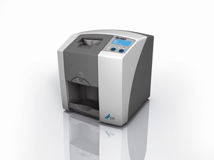
“The Durr CR 7 is a newly introduced desktop scanner which is ideal for critical inspections mainly with small imaging plates. The size of the imaging plates for this scanner can be from 2x3cm and go up to 6x10cm.It is perfect for both on site and in house inspections due to its compact size. It has an adjustable laser focal spot (12.5µ- 50µ) that enables the system to involve wide range of applications. Specifically designed High Spec’ PC and the Durr D-Tect software platform for NDT Radiographic application go well with this system. The system is very fruitful for volume applications as the scanning of small imaging plates is done rapidly even at high resolution” (Computed Radiology 2007, Para 12).
NDT Experiments
Pulsed Eddy Current experiment
“The following experiment was developed at the Air Vehicle Research Detachment, Department of National Defense, Ottawa. The conclusions drawn on the basis of pulsed eddy current experiments performed on laboratory and in-service multi-layered samples are illustrated in a coherent manner in different ways such as A-scan spot measurements, the one-dimensional time-based B-scan and the 2-dimensional C-scan image formats” (Lepine et al 1999, Para 12).
Pulsed Eddy Current System Setup
A diagram of the experimental set up is shown in the figure down. “This set up has a provision of producing pulsed eddy current signals the transients generated through these signals are measured on getting affected by flaws in scanned specimens” (Lepine et al 1999, Para 12).
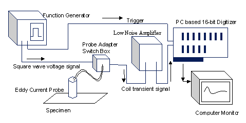
“The system is based on a technique initially developed by Moulder et al. In this system the voltage is dropped across a resister and fed into a low noise amplifier” (Lepine et al 1999, Para 12) “The signals that are reproduced through this process are measured and then digitized by a PC based data acquisition system” (Lepine et al 1999, Para 12).”For data acquisition The WinspectTM software by Utex Scientific Instruments, Inc. was used and the signals were displayed in the form of A-, B-, or C-scans. Signals were analyzed and thereafter processed with the help of NDI Analysis, a software package developed at NRC/IAR” (Lepine et al 1999, Para 12).A number of probe-coil patterns can be held in this system (Lepine et al 1999).
- A single complete coil for driving and receiving the EM Field transients.
- Another arrangement where two coils can be used. Each is used for either driving or receiving.
- A set up where differentiation can be drawn by putting one coil on a reference standard and the other is used to run across a test specimen.
“All the tests were conducted with the help of three probes. a)A single air-core coil, b) a stacked D/P(driver/pick-up) in which on air-core coil is put above another same type of coil, c)and another D/P probe in which a driver coil is placed and a smaller 1.6mm ferrite-core receive coil is placed co-axially within it” (Lepine et al 1999, Para 12).
“The driver coil of all probes has a14mm outer diameter. Probe ‘c’ has a pick-up coil having 6.35mm outer diameter. A centre frequency of 12kHz was fixed for the functioning of these probes” (Lepine et al 1999, Para 12).
“The Probe Adapter Switch Box is used to determine the selection of the mode of operation and the resistor which is used for measuring the signals across it. This feature provides flexibility to this system. The received signal amplifier is facilitated with varied gain settings ranging from 1X to 50,000X.The function generator modifies the drive voltage which may range from 1to 30 volts and waveform shapes. The settings in the system are determined mainly by the limitations of the probes and the nature of specimens” (Lepine et al 1999, Para 12).
Specimens: “For constructing the calibration test specimens, 1 mm thick 2024-T3 aluminum alloy sheets were used. These sheets are normally used for constructing the aircraft fuselage skin structures. A 100 mm x 300mm aluminum alloy sheet was divided into 25mm wide strips that were cut to different depths from 0.05mm (5%) to 0.46mm (46%)” (Lepine et al 1999, Para 13).
According to Lepine et al (1999) another sheet without any damage was taken to be kept under this sheet for the replication of thinning due to corrosion on the lowermost side of the first layer. This combination is reversed for replicating thinning on the top of the second layer. These paper strips were kept between the metal sheets in a gradually increasing number that stand for the uneven gap between two integral layers of the metal. A micrometer was used for measuring all gaps, milled areas and thickness of the sheet. “For the second specimen a retired Boeing 727 was selected. The fuselage lap splice with hidden natural corrosion, detached from it was taken as a sample. The skin structure of this sample comprised of two 1.27 mm thick 2024-T3 Al sheet with a stringer” (Lepine et al 1999, Para 13).
Experimental Procedure: The complete range of tests was carried out with the help of a function generator producing a simple 1kHz bipolar square wave. The signal which was received was recorded at 16 bits (Lepine et al 1999).
“The function generator was used to produce a simple 1 kHz bipolar square wave throughout the complete range of tests. The received signal was recorded at 16 bits precision with a 1 MHz sampling rate. The first half of the intermittent signal was recorded at each point. The specimens were made to travel in a raster pattern with the help of an automatic scanning table. The probe was held in place during the procedure” (Lepine et al 1999, Para 13).
“The produced area enables the scanning from 7500 to 15000 mm2 per specimen taking only 3-5 minutes for each. As the data was captured during comparatively fast area scans the signals were not averaged” (Lepine et al 1999, Para 13).
“One reference signal was chosen from the material which comprised of only two 1mm thick metal sheet at a location indicating no defect. This reference signal is deducted from the other signals produced at the remaining locations of the scan. Winspect(tm) and/or NDI Analysis are used for this purpose. These reference signal deducted signals form a set, which is also known as A-scans, represent the discontinuities because of the flaws or other anomalous conditions” (Lepine et al 1999, Para 13).Using time gating and feature collapse functions on the A-scan data, B-scans and C-scans were taken out (Lepine et al 1999).
Results and Discussion
“All the three probes were used in the scanning of the calibration specimens thereafter the results were stored in digital format with the help of Winspect ™” (Lepine et al 1999, Para 14).
“Scanning calibration specimens allows one to view the effects of known The structural changes such as thinning and substructure in a material can be inspected by scanning calibration specimens. The results illustrated that all the three probes had successively in detected various amounts of thinning. The strongest response was derived from probe ‘c’ because of its smaller pick-up coil. Here we have presented the conclusions drawn from probe ‘c” (Lepine et al 1999, Para 14).
A-scans
According to Lepine et al (1999) in figure 25 there is an illustration of the transient signals which are measured by the pick-up coil. These can be used for different test parameter or material conditions. In response to the varying magnetic field on the material surface current is induced into the coil. The curves can be taken as virtual measurements of this current. Complete information about the incident fields and the replicated fields is gathered through these signals. It is apparent that there is only a slight deviation in the shape and amplitude of the signals even for those test conditions that vary tremendously.
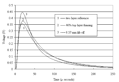
Lepine et al (1999) mention that the illustration of the A-scans is presented in the figure 26. The signals, indicating the flaws, have certain features which may help in characterizing definite flaw parameters, such as the setting parameters for the influenced layer, its depth and percent metal loss. These parameters influence the signal’s amplitude and its time-to-zero-crossing (TZC) greatly.
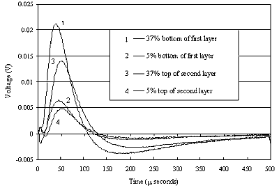
The results found by Moulder et al have been replicated in these experiments. The objective is to demonstrate the characteristic quality of the A-scans in exemplifying their capability in distinguishing the different locations of thinning. “The difference between the first and second layer thinning is that the first layer has earlier TZC than the second one, as expected. Since the large amounts of thinning in the first layer has its metal/air borders increasingly closure to the surface the signals are expected to have earlier TZC. The TZC remains comparatively stable for all sizes in the second layer thinning as their metal loss has no moving metal/air border” (Lepine et al 1999, Para 15).
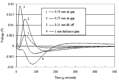
Quite a few structural discrepancies which are not related with corrosion or other defects come across in the scanning of a typical aircraft. It increases the complexities encountered during the inspection. As an instance, the negligible amounts of plate separation, of course not due to corrosion, may affect the PEC signals. “In real aircrafts these “benign” air gaps are produced because of the presence of scrim cloths, and minor bulging or warping around rivet in its components which may delude the signals” (Lepine et al 1999, Para 15). “Besides this, the changes in the substructure like the increase in metal thickness on coming across the stringers also may delude the signals” (Lepine et al 1999, Para 15).
The difference produced by all these test conditions is illustrated in below mentioned figure. The earliest TZC and the largest amplitude is displayed by the Lift-off signals. There is a peculiar reverse shape is shown for the increasing metal thickness signal. It is to be noted that these signals have their own distinctive qualities, like the varying TZCs. The concurrent occurrences of these differences may affect the lucidity of their analysis and interpretation. It is very difficult to distinguish between the signals on the basis of their virtual features is a complicated task. “It is discovered by the preliminary experiments that these differences, with respect to thinning, cause the previously calibrated flaw signals of Figure 26 shift earlier in time” (Lepine et al 1999, Para 16).Therefore, it is important to examine their combinations before reaching to a more dependable and organized approach to differentiate between these concurrent features.
C Scans: The data received from the information selected from scan an A-scan is viewed in an image format known as C-scan. A definite portion of the A-scan data is selected for analysis with the use of time gates. For instance the TZC of a certain section of A-scan can be generated as a C-scan image. It is noteworthy that the section of selected A-scan should be corresponding to a series of depth in the specimen (Lepine et al 1999).
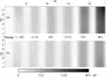
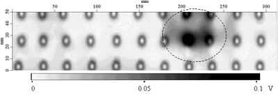
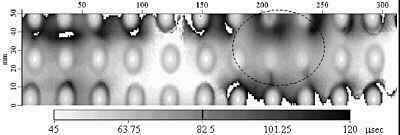
“In the figure 28 there is an amplitude C-scan illustration for the calibrated specimen in which thinning in the bottom of the first layer and top of the second layer has been tested” Lepine et al 1999, Para 18).These scans make it clear that the corrosion level detection of the single layer thickness by the PEC system can be as low as 5%.Whereas in figure 6 &7 deep information is made available by the TZC C-scans. These scans manifest the difference between the defects found in the two layers. It is noteworthy that a small amount of separation may have caused the TZCs in Figure 6(b).Moreover, the TZCs C-scans could be noisy because of the noise fluctuations crossing the zero axis a number of times in case of weak signals.
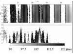
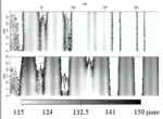
B-scans: The B-scans in Figure 30 present a liner cross section with the help of a C-scan. The calibration samples are same. A linear cross-section is depicted through a C-scan. The time scale can provide valuable information in this case. So, the illustrated B-scans also enable us to differentiate between first layer and second layer thinning (Lepine et al 1999).

According to Lepine et al (1999) the depth of the flaws at each position is interpreted by marking the shift in TZC. Same experimental setting and probes were used for the scanning of the material detected with corrosion.An extreme corrosion movement is exposed by the amplitude C-scan image. There can be seen a more chaotic state in the TZC C-scan in Figure 32 due to the stringer through the center row of rivets.
Conclusions
“It is evident that a correct analysis of PEC scans can provide considerable information which is essential for characterizing corrosion in aircraft structures. The time-based signals are more sensitive and can be demonstrated in various formats presently used in ultrasonic NDT. Simple variations in test simultaneous occurrences cause confusion. A sensitivity of minimum 5% total metals loss, or 0.05mm thinning in the second layer was established by the PEC system. Probe lift-off and specimen layer separations are comparatively more difficult to manage. The flaw information is also detached in the process of simply gating out transient responses with early zero-crossings for such differences” (Lepine et al 1999, Para 22).
Magnetic Particle Experiment
This experiment was carried out in order to assess the effect of wet magnetic fluorescent particles, applied on stationary test equipment. The objective of this experiment was to investigate quantitative and qualitative occurrence of the Fluorescence background’s increasing during the Wet Magnetic Particles inspection. “The experimental research was carried out by ENEA (Energy Centre Research), Italian Institute of Welding and NDT Italiana Society.
The aim is to prove the authenticity of the Photo fluorimeter NDT-S291 mentioned in the ASTM-E-1135, for effective fluorescence measurements of Fluorescent Penetrants” (Calcagno et al 2000, Para 1).
“Different standards, e.g. MIL-STD-1949, DOD-F-87935, Rolls-Royce Specification-RPS.700, etc. were taken into account which is used constantly in the aircraft and Space Industries. This experiment involved a number of operators and which were positioned in different locations having no contact with one another to ensure maximum reliability and fairness. Different products were used in different locations” (Calcagno et al 2000, Para 1)
Equipment and specimens
The experiments were carried out at laboratories of ENEA (Energy Centre Research), of Italian Institute of Welding and of NDT Italiana Society (Calcagno et al 2000).
Test Samples
“The samples detected with defects like hot cracks, cold cracks, heat treatment cracks, tension-corrosion cracks and fatigue cracks were used for inspection” (Calcagno et al 2000, Para 2).
Products
“The analysis involved Wet Magnetic Fluorescent Particles manufactured by four different manufacturers. These particles are denoted as “A”, “B”, “C” and “D” in the figure below. These particles present two different powder dimensions (2-5 m and 5-10 m) suspended in oil-based fluid” (Calcagno et al 2000, Para 1).
Magnetic Equipment
To make use of different kinds of alternate and corrected current in this experiment a special kind of magnetizing bench was utilized (Calcagno et al 2000).
Photofluorimeter and UV(A) Lamp
“To validate that the fluorescence does not change under ultraviolet exposition A 100W U.V. lamp with separate Wood Filter was used in combination with a radiometer type UVR-365 and a luxmeter type LUX-MET was used” (Calcagno et al 2000, Para 1).
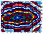
“The S291 Photofluorimeter mentioned in the ASTM-E-1135 for Fluorescent Penetrants was used to analyze the fluorescence intensity” (Calcagno et al 2000, Para 2).
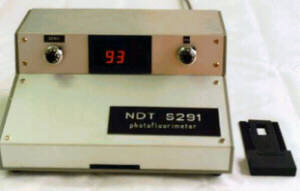
The Fluorescent Penetrants were modified conveniently and calibrated to allow maturing in both the magnetic particle fluorescence and the liquid fluorescence
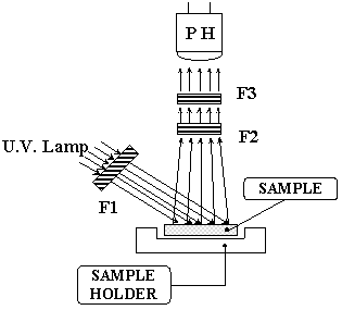
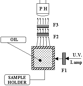
Analysis and Results
“Before starting the test several mechanism and distinctiveness of the Photofluorimeter were confirmed. The ultraviolet light emission spectrum of the U.V. lamp of the Photofluorimeter and its transmission spectrum of filters was measured with a monochromator having the measuring capability in the 200-800·nm range” (Calcagno et al 2000, Para 3).
“The results emphasize that the maximum U.V. emission occurs at 366 nm wavelength. This condition is most favorable for activating Fluorescence, as an excitation wavelength of 365 nm is usually required” (Calcagno et al 2000, Para 3).
“Subsequently, the evaluation of the magnetic particles’ fluorescence after a long exposition to U.V. radiation using the fixed magnetizing equipment was conducted. some samples of Dry Magnetic Fluorescent Particles are evaluated before and after two hours of U.V. exposition, at 1000 m W/cm2 of intensity measured on the test surface” (Calcagno et al 2000, Para 3).
“This figure illustrates a considerable difference of the results obtained for particles of same dimension but different manufacturers, using traditional Photofluorimeter” (Calcagno et al 2000, Para 3).
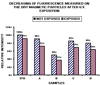
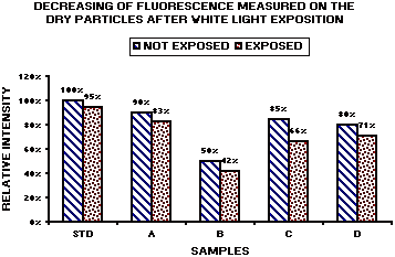
The below figure shows the exposition effects on the Magnetic Particles’ Fluorescence. “As the figure shows that the fluorescence has decreased considerably when kept in white light exposition, in the storage conditions, for 24 hours. Next the products were tested for a long working period to assess the resistance of the fluorescent pigment in the condition of erosion and corrosion action due to the fluid” (Calcagno et al 2000, Para 4).
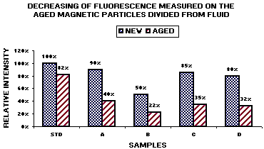
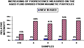
Calcagno et al (2000) mention that a decrease in the Magnetic Particles’ Fluorescence after 400 hours is demonstrated in the down mentioned figure that shows the increasing of Liquid’s Fluorescence within the same time period.
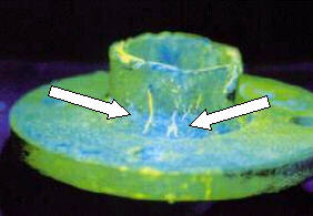
Now, the considerable impacts of the product’s aging on the sensitivity of the NDT process were tested. Some natural defects were selected as samples. After a long period of 400 hours some products were in a position to be used. The remaining products were not able to denote any significant defects. (
Summary
The Non Destructive Testing field has an important place for the Magnetic Particle Testing. There is a great need to examine the critical components applied in aerospace, petrochemical or nuclear industries. The soundness of the Fluorescence’s measurements is dependent on the test procedure and the productive and functional uniqueness of the instrument used in this procedure (Calcagno et al 2000). Long U.V. radiation and white light exposition caused decrease of the Fluorescence, on new dry Magnetic Particles.
The aging test shows that there is an immense relation between the fluorescence’s decreasing of the dry magnetic particles and the increasing of liquid’s fluorescence. “Hence, the findings of this experimental research prove the technical appropriateness and practical dependability of Photofluorimeter NDTS291, mentioned in the ASTM-E-1135 to compare different Fluorescent Penetrants. These experiments also verify the Fluorescence’s characteristics of Magnetic Particles” (Calcagno et al 2000, Para 5).
Conclusion
The post World War II period pronounced the requirement for more and more testing equipment so that flawless components could be manufactured at a fast pace. So, Non-Destructive Testing instruments were developed and new advancements has constantly been in progress in this field (Deutsch 2000).
Like other transportation industry aviation industry also requires to have greater safety measures. The aircraft parts are designed in such a manner that they carry much heavier loads than their material potency. This is expected that the components develop some flaws in course of time because of the cyclic stress experienced during landing, flying taxiing and pressurizing the cabin. “Besides the ”fatigue cracks” lightning strike can also cause sometimes even though they are protected against it” (Nondestructive Testing in the Aerospace Industry n.d., Para 1).
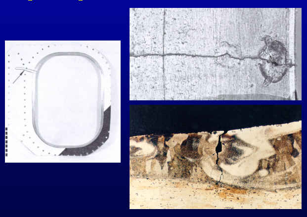
The problem of corrosion often exists in the aircrafts in course of time. The warm moist air enters inside an aircraft when the door is opened after landing. This condensed air causes collection of water at low areas and eventually corrosion takes place. The NDT aims at detecting the flaws while they are within tolerable limits so that appropriate measures can be taken in time (Nondestructive Testing in the Aerospace Industry n.d.). NDT provides minute inspection of all the parts of an aircraft including those which cannot be visualized or the internal areas which cannot be inspected without the disassembling of the structure.
According to Pizzo (2010) in designing and manufacturing process of a product whether it is manufacturing process, choice of materials, research and development, congregation, quality control and maintenance NDI plays a very significant role. The aviation industry is dependent on NDT for its success since it is very effective in reducing the cost of maintaining and flying aeroplanes.
Reference List
Aziz, A. A. et al (2005) Applicability of a Crack-Detection System for Use in Rotor Disk Spin Test Experiments Being Evaluated [Online]. Web.
Calcagno G et al (2000) Characterisation of Magnetic Fluorescent Particles: The Last Results According to the Available Standards [Online]. Web.
Computed Radiology (2007) [Online]. Web.
Computed Radiography Systems (2006) Siemens Medical [Online]. Web.
Deutsch I V (2000) History of NDT-Instrumentation [Online]. Web.
Ferreira J P et al (2011) Comparison of infrared thermography and shearography for nondestructive evaluation of composites materials by pulsed-heating excitation [Online]. Web.
Godbole, U & Gokhale A (2006) Eddy Current Inspection in Aircraft Industry [Online]. Web.
Industry: Gamma- Radiography (n.d.) [Online]. Web.
Ingold, B J (n.d.) Selecting a Nondestructive Testing Method, Part VI: Thermal/Infrared Inspection Techniques – Thermography [Online]. Web.
Khan, A U (1999) Non-destructive Testing Applications in Commercial Aircraft Maintenance [Online]. Web.
Kohli, A (2012) Computed radiography-finally an affordable technological advancement for conventional radiology?. Indian J Radio Imaging [Online] Web.
Kotambkar, M S (2010) Exploring Vibration Based Method for Crack Detection in Turbine Blade, 20I0 International Conference on Mechanical and Electrical Technology (ICMET 2010)
Lepine, B A et al (1999) Pulsed Eddy Current Method Developments for Hidden Corrosion Detection in Aircraft Structures [Online] Web.
Maintenance and Repairs: Crack Detection (n.d) [Online] Web.
Maldague, X (n.d.) Applications of Infrared Thermography in Nondestructive Evaluation [Online] Web.
Measurement and Control (2012) [Online] Web.
NDT Certification (2010) [Online] Web.
NDT Method Summary (n.d.) [Online] Web.
Nelligan, T (2011) Ultrasonic Flaw Detection [Online] Web.
Nondestructive Testing in the Aerospace Industry (n.d.) [Online] Web.
Pizzo P P (2010) Exploring Materials Engineering [Online] Web.
Shearography: Non Destructive Testing (NDT) (2008) [Online] Web.
Shreagraphy (n.d.) [Online] Web.
Snell, J R & Spring, R W (2007) Infrared Thermography Advances [Online] Web.
Standard Practices and Structures (2011) A 340-200/-300’ 2011 Nondestructive Testing Manual
Swiderski W (n.d.) Nondestructive Testing of Composite Materials for Military Applications by in Thermography Methods [Online] Web.
Tober, G & Schiller D (2000) NDT in Aerospace: State of Art [Online] Web.
Wallenwein, D H (1997) Industrial X-ray 1895 until today [Online] Web.
Willcox, M & Downes G (2003) A Brief Description of NDT Techniques [Online] Web.
Wishaw, M (n.d.) Notes on the Industrial Technologies for Crack Detection and Condition Monitoring [Online] Web.