Introduction
As a method of thermal recovery, the process of cyclic injection involves injecting a well with steam, after which its use is subjected to subsequent production. There are three stages involved in a complex process of cyclic steam injection, which is an injection, soak phase, and production of thinned oil. The first stage involves the injection of a slug of steam into a reservoir. The second phase involves soaking the slug by shutting the well for days to ensure even heat distribution, which then thins the oil. The last stage involves producing the thinned oil via the same well (Abdulaziz et al. 21).
The cycle is then repeated as long as oil production remains viable. This part of the report will explore the process of cyclic steam injection. Specifically, this section will discuss each stage and illustrate the entire process from the first to the third phase.
Cyclic Steam Injection
Cyclic steam injection has become a common process of heavy crude oil extraction. This method falls under the thermal oil reservoir stimulation approaches and is considered an enhanced form of oil recovery (EOR) (Temizel et al. 17). At present, cyclic steam injection is widely used in Northern Alberta’s oil sands in Canada, Lake Maracaibo in Venezuela, and San Joaquin Valley in California State. Cyclic steam injection is known to enhance oil production due to its near-wellbore cleanup (Ivan et al. 27). This means that the steam is capable of reducing the viscosity by tying asphaltene and paraffin to the surface of the rock (Temizel et al. 19). At the same time, crude oil steam distillation creates a solvent bank that able to miscible remove any trapped oil.
Process of Cyclic Steam Injection
Also known as the Huff and Puff technique, the process of cyclic steam injection involves injecting, soaking, and production of oil, as discussed below.
Stage 1: Injection
The injection phase commences with injecting steam into a well for a specified duration in order to heat the oil within the surrounding reservoirs with the intention of recovering at least 20% of the Original Oil in Place (OOIP). Steam injection into a well is regulated within the temperature range of 300°C and 340°C (Temizel et al. 23). The injection period may be between weeks and months, depending on the intended production capacity. The steam injection process is done under high pressure and temperature to ensure inter-well flow resistance does not interfere with the injection rate.
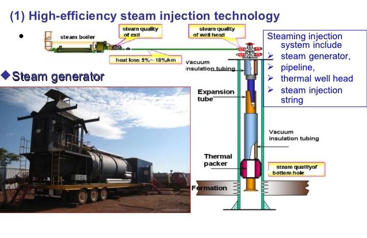
The injection string comprises a vacuum insulated tubing (pressure of 21MPa and thermal conductivity of 0.02-0.007W.m/ °C), thermal sensitive packer, and a compensation pipe. The ideal heat conduction coefficient should be 0.007W.m/ °C to increase the quality of steam and minimize heat loss within the wellbore. During the process of steam injection, the set down thermal sensitive packer will extend the insulated tube as a result of high temperature (see figure 1). Therefore, the compensation pipe is utilized to balance the length of the extended injection string to prevent the insulation tubing from bending (Ivan et al. 29).
The thermal-sensitive packer is used to preserve the casing and reduce potential heat loss during steam pumping. Due to thermometer expansion at the onset of injecting stream, the packer might set down. However, its seal will go back to the factory setting automatically (Temizel et al. 28). The steam injection system is comprised of a pipeline, steam generator, thermal wellhead, and the injection string.
Stage 2: Soak Phase
When enough steam has been injected at the right temperature and pressure into the well, the second stage of cyclic steam injection begins with tightly shutting the well to give the steam enough time to soak and heat as much oil as possible in the reservoir. Tightening the well is necessary to maintain the right pressure and temperature during the period of soaking the crude oil (Temizel et al. 22). For instance, in a good reservoir with high viscosity, shutting the well will ensure that the inter-well flow resistance is minimized so as to enhance the good pressure. In order to optimize the soaking process, the well should be left tight for at least five days.
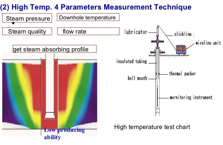
This is necessary to provide effective and adequate time for steam flooding in addition to improving the economic efficiency in oil extraction (Ivan et al. 18). The parameters used to measure the temperature in the second phase are steam pressure, flow rate, steam quality, downhole temperature, and absorbing profile (Sarma et al. 14). Therefore, the insulating tubing should remain tight to ensure that these parameters are constant.
Step 3: Oil Production
This stage commences immediately after the shut well is opened. Production of oil begins when the well is unsealed. Hot oil will puff out from the well. Due to buildup pressure and heat connection, hot oil can be easy pumped out for refining (Temizel et al. 17). This process is repeated as many times as possible, especially when oil production is viable.
Conditions Applicable in Cyclic Steam Injection
In order to make the cyclic steam injection process successful, the caprock should be relatively thick to endure the pressure from the high steam injection. Moreover, the crude oil should be in a movable state for ease of flow during pumping. The caprock should also have high porosity and permeability for optimal oil dissolution. Moreover, the reservoir should have drive energy, a gas cap, and no water at the bottom of the well (Ivan et al. 27).
In addition, the existing net pay zones in the well should be more than 15 meters thick. This means that an effective cyclic steam injection process occurs when the reservoirs are capable of accommodating steam injected at a high injection rate of 200 m3/d (Zou 4). At the same time, there should be adequate energy to push oil to wellbores. There are selection standards or guidelines that should be followed to ensure a successful cyclic steam injection. These standards define the depth, porosity, permeability, oil saturation, and viscosity standards (see table 1).
Table 1: Conditions for successful cyclic steam injection.


Summary
The cyclic steam injection process involves three stages, which are steam injection, well soaking, and actual production. In a horizontal well, this process has a higher success rate than other techniques due to improved sweep efficiency and reduced cost of directional drilling. This process is also associated with good results, especially in the event of a low permeable well. However, the entire process should only be repeated when the oil production process is viable and efficient. This means that the cyclic steam injection should be subjected to continuous evaluation while factoring in the aspects of fluid interaction, mineralogy, and other reservoir properties.
Works Cited
Abdulaziz, Najaf, et al. “Steam Injection Tracking System.” SPE/IATMI Asia Pacific Oil & Gas Conference and Exhibition Held 2015 at Nusa Dua, Bali, Indonesia, edited by Society of Petroleum Engineers, South Asia Office, 2015, pp. 1-35.
Ivan, Kuvshinov, et al. “Analysis of Chemical Compositions Injection Combined with Cyclic-Steam Stimulation.” SPE Russian Petroleum Technology Conference Held 2018 at Moscow, Russia, edited by Society of Petroleum Engineers, Russian and Caspian Office, 2018, pp. 1-42.
Sarma, Pallav, et al. “Cyclic Steam Injection Modeling and Optimization for Candidate Selection, Steam Volume Optimization, and SOR Minimization, Powered by Unique, Fast, Modeling and Data Assimilation Algorithms.” SPE Western Regional Meeting Held 2017 at Bakersfield, California, edited by Society of Petroleum Engineers, Houston Office, 2017, pp. 1-29.
Temizel, Cenk, et al. “Optimization of Cyclic Steam Stimulation (CSS) Under Geomechanics-Dependent Permeability.” SPE Russian Petroleum Technology Conference Held 2015 at Moscow, Russia, edited by Society of Petroleum Engineers, Russian and Caspian Office, 2015, pp. 13-44.
Zou, Caineng. “Steam Injection.” ScienceDirect. Web.