Introduction
Among other uses, water is a coolant in petroleum refineries and, as such, is consumed in large volumes by these companies. The refining process generates a significant amount of wastewater, which contains hazardous chemicals such as hydrocarbons that make its disposal a challenge to refineries. ROW reclamation is an attractive solution to these refineries in dealing with the wastewater they generate. In addition, there is an increasing demand for fresh water as the global population increases, as such; reclamation of wastewater is gaining recognition, acceptance and popularity as a significant, growing and reliable water source (Ismail and Yuliwati 2).
Wastewater management ensures that this demand is met at an acceptable financial and environmental cost (Ismail and Yuliwati 2). It, thus, determines the apt wastewater reclamation technology to employ for a given case. Robust wastewater reclamation technologies are apt, sustainable, easy to maintain and efficient in eliminating the hazardous chemicals and pathogens in wastewater (Ismail and Yuliwati 2).
ROW is effluent discharged out of petroleum refineries that is an emulsion of water and oil and which additionally contains heavy metals, organic contaminants, inorganic contaminants, salts, aromatics, grease, phenol and ammoniacal nitrogen among other substances (Lenntech). Table 1 in appendix A shows the common contaminants in ROW. Samples of refinery wastewater taken from different refineries reveal that one of its physical characteristics is that its parameters are extremely variable meaning that different samples contain different chemical substances and have varying chemical substance concentration (Saudi Aramco 14). Another physical characteristic of refinery oily wastewater is a high temperature ranging between 30 – 50˚C (Saudi Aramco 14). The other of its physical characteristics is a highly variable rate of flow (Saudi Aramco 14). Refinery oily wastewater reclamation involves treatment of the waste water and its reuse.
Discussion
Various refinery oily wastewater reclamation technologies are in use today in various parts of the world. Petroleum refineries are interested in reclamation technologies that will enable them meet the strict effluent quality standards set by authorities. They are again interested in technologies that guarantee them a reliable supply of fresh water and that cut on operational costs while maintaining high quality of effluent (Peeters 3).
Existing processes
Gravity separation
Gravity separation is one of the technologies used to treat ROW (Koytsoykos 5). Gravity separators perform primary ROW treatment by creating an environment that facilitates the settling down of suspended solids and that facilitates clarification of oil from the rest of the influent (Koytsoykos 5). Though effective in separating free oil from water, gravity separators do not separate dissolved contaminants or demulsify the emulsions present in the influent. This is there main disadvantage. A commonly used gravity separator in ROW treatment and reclamation is the API. The API consists of an open rectangular-shaped basin, an inlet and chambers for oil-water separation (Koytsoykos 6). An advantage of the API separator is its large volume that allows it to cut-off large amounts free oil and suspended solids. The large volume of the API separator is also again one of its disadvantages because necessitates the need for a large areas of land (or implementation space). Another disadvantage of the API separator is that it is only effective in removing relatively large droplets of oil.
Another commonly used gravity separator is the break tank. A break tank holds influent for as long as is sufficient for free oil to float to the surface and for heavy-than-water oil and solids to settle at the bottom (Koytsoykos 6). The free oil that settles at the surface of the break tank is skimmed. An advantage of using break tanks is that they facilitate flow balancing whereas they main disadvantage is that they have compatibility issues with treatment systems that already use API separators. The quality of water treated using gravity separators still contains high concentration of contaminants and does not meet discharge limits and therefore has no practical reuse application.
Flotation
Flotation is another of the technologies used to treat ROW (Koytsoykos 8). Flotation devices, if compared to gravity separators, perform advanced gravity separation, which is categorized as secondary treatment of influent (Koytsoykos 8). They are particularly effective when weak bonds exist between contaminants. Gas bubbles in the influent provide the buoyancy needed to float the oil once there are weak bonds. Once the afloat the oil is skimmed. DAF and IAF are the two main types of flotation devices (Koytsoykos 8). DAF flotation devices are particularly effective in on–shore ROW treatment whereas IAF are effective in off-shore ROW treatment. To trigger buoyancy IAFs have to pump air into the influent, however, this is not necessary with DAF because they handle influent which has sufficient amount of air (or gas) to trigger buoyancy.
Flotation devices are strategically located between gravity separators and biological treatment systems (Koytsoykos 8). With this arrangement, flotation treatment has the potential to remove all remaining free oil and suspended matter from the influent being treated (Koytsoykos 8). These potential can be realized through proper design and operation of flotation devices. An advantage of flotation is that it produces oil that is stable. Another advantage of flotation treatment is that it increases the dissolved oxygen content of the treated effluent. A disadvantage of flotation devices is that they are not effective in removing dissolved substances.
Filtration
Filtration is another of the technologies used to treat ROW. A filter is according to Koytsoykos “a supported bed of granular media (usually sand, anthracite, garnet or a combination of these or nutshells) through which effluent water is passed to remove non-dissolved material.” (10). Filters are effective in the removal of un-dissolved oil which for some reason was not removed during flotation. Filters are also effective in the removal of suspended solids. Flocculation improves the performance of filtration treatment especially when polymer flocculants are used e.g. 3530s. Koytsoykos further points out that granular-media filters are “differentiated in several ways – mode of operation (downflow or upflow), pressure or gravity, number of media materials in the bed, material of media and depth of penetration of the contaminants”.
In a MMF the granular media is chosen and arranged such that the filter has large sized pores at the influent end and small sized pores at the effluent end (Koytsoykos 10). Thus, the level of filtration in the filter increases as you move from the influent end towards the effluent end. MMC filters frequently require cleaning to prevent pressure drop that can cause contamination of the treated wastewater stream (Koytsoykos 10).
An advantage of MMC filters compared to CSWF is that the risk of filtrate contamination is low. A disadvantage of MMC filters when compared to CSWF is that they require a considerable amount of supervision. CWSF filters perform quick up-flow filtration and are according to Koytsoykos “based on continuous sand washing”. Influent goes in at the bottom end of the filtering bed and effluent comes out at the upper end of the filtering bed. The sand that makes up the filtering bed is continuously and mechanically cleaned. An advantage of CSWF filters over MMC filters is that they require minimal supervision and give a stable (consistent) performance. A disadvantage of CSWF compared to MMC filters is that they require a large amount of wash water and they have a higher risk of contaminating filtrate.
Flocculation
Flocculation is another technology that has been used to treat ROW. It has been used at YPC to pre-treat ROW as it awaits ultra-filtration done using a ceramic membrane (Zhong, Sun and Wang 93). Experimentally, flocculation has been proved to reduce oil content and COD in ROW significantly (Zhong, Sun and Wang 93). The ROW for the pilot experiment obtained from YPC’s refinery plant had the parameters shown in table 2 in Appendix A. The pilot lab experiment involved adding a flocculent to 200ml of the sample ROW then electrically stirring the mixture for a given period of time and finally allowing the mixture to stand for a certain amount of time. The electronic stirrer was set and maintained at a certain temperature. Flocculants for the experiment were provided by YPC’s refinery plant.
To determine the flocculent with the highest flocculation efficiency with this sample of ROW 6 flocculants were tested on 250 ml of this sample of ROW at a flocculation temperature of 25 °C yielding the results shown in table 3 in appendix A. Their dosages, stirring time and holding time are also shown. On the basis of these results, 3530s, a derivative of polyacralymide, emerged as the best performing flocculent (Zhong, Sun and Wang 94).
Experimentally, the effect of flocculation factors, namely, dosage, stirring time, holding time and temperature on the performance of 3530S were investigated in order to determine the combination that facilitates optimal performance of this flocculent (Zhong, Sun and Wang 95). Three investigative levels were chosen. The selection of these levels had its basis on the oil content of the sample ROW. The reason being that oil is more challenging and important to treat than COD. The levels chosen are shown in table 5 in appendix A. A total of nine pilot experiments were undertaken to investigate each level.
The experiments were arranged in the manner shown in table 4 in appendix A. After analyzing the results of these experiments, the combination that gave optimal performance was a flocculent dosage of 70mg/l, a stirring time of 90 minutes, a holding time 90 minutes and a temperature of 40°C (Zhong, Sun and Wang 95). In the pilot experiment, though flocculation using 3530S reduced significantly the oil and COD content level the Chinese National Discharge Limit was not met. Thus, the effluent from flocculation treatment was subjected to ultra-filtration using a ceramic membrane (Zhong, Sun and Wang 93).
Electrocoagulation
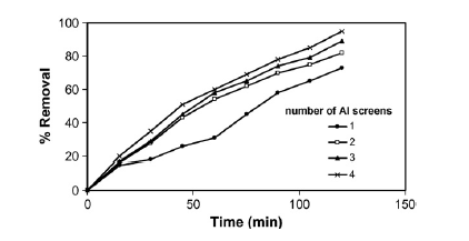
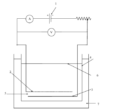
Electrocoagulation is another process that treats ROW and is particularly effective in the removal of phenol, which is one the most common contaminants in ROWs (Abdelwahab, Amin and El-Ashtoukhy 711). The process uses a electrocoagulation cell with an aluminium anode and cathode. Furthermore, the thickness of the anode is adjustable (Abdelwahab, Amin and El-Ashtoukhy 711). Two sub processes exist in this main process. These are sweep coagulation and adsorption (Abdelwahab, Amin and El-Ashtoukhy 711). These two sub-processes working together have the potential to remove 97% of the phenol present in a unit volume of ROW in a time of 2 hours. For this to happen the electrocoagulation cell has to create a high current density in the ROW which in turn has to have a PH value of 7 (Abdelwahab, Amin and El-Ashtoukhy 711). Electrocoagulation rate increases as the phenol concentration reduces. The electrocoagulation cell performs better at any current density when its anode is an array of multiple aluminum screens that are closely packed together instead of when it is a single screen. This is because this arrangement prolongs the life of the anode (Abdelwahab, Amin and El-Ashtoukhy 711).
Phenol is a non biodegradable and toxic compound that has been rated as a priority pollutant because even in low concentration it poses a threat to organisms and human health. Environmental authorities have set stringent discharge limits for phenol in wastewaters, for instance, the EPA in the US requires treated wastewaters to have no more than 1 mg/l concentration of phenol (Abdelwahab, Amin and El-Ashtoukhy 711). Electrocoaugulation is defined by Abdelwahab, Amin and El-Ashtoukhy as “the process utilizing “scarified” anodes to form active coagulant which is used to remove pollutant by precipitation and flotation in situ” (711).
An advantage of electrocoagulation over chemical coagulatation is that the former can remove finer particles of phenol in ROW than the latter. This is because the electric field from a electrocoagulator causes mobility of particles thus encouraging further coagulation. Another advantage of electrocagulation is that the quantity of sludge it produces is relatively small compared to that produced by other treatment processes. Another advantage of electrocougulation is that it does not generate harmful by-products as is the case with other treatment processes. Another advantage of electrocoagulation is that it is very economical on space that is, the process does not need a lot of physical space to implement. A disadvantage of electrocoagulation is that it is an energy consuming process and such increases energy costs. The other disadvantage of electrocoagulation is continual replacement of electrodes, which is a costly undertaking.
Electrocoagulation occurs in three main steps (Abdelwahab, Amin and El-Ashtoukhy 711).
- The first step is characterized by electrolytic reactions that occur at the anode and cathode surface.
- The second step is characterized by
- the in situ oxidation of Aluminum ions that were formed during the electrolytic reactions of the first step and
- the formation in aqueous phase of an aluminum hydroxide precipitate.
- The third step is characterized by coagulant adsorption of soluble and/or colloidal contaminants. The coagulants are later removed by sedimentation or flotation.
In the pilot experiment, to determine the effectiveness of electrocoagulation in the removal of phenol sample ROW was taken from SIdi Kerir Petrochemical Company in Egypt (Abdelwahab, Amin and El-Ashtoukhy 712). It had the chemical parameters shown in table 10 in appendix A.
The experimental apparatus used was a electrocoagulation cell whose schematic diagram is shown in figure 1 in appendix B. The anode of the cell was made of aluminum screening whereas the cathode was made of oriented aluminum. The cell treated the sample ROW for two hours at a current density of 23.6 mAcm-2 and a PH of 7.The chemical parameters of the resulting effluent are shown in table 10 in appendix A. The result shows a 94.5% removal of phenol form the sample ROW. Other contaminants in the sample ROW remained excessively unchanged. Notably, phenol concentration in a litre of the effluent met EPA’s discharge limit. This result was achieved at an energy consumption rate of 1.8 kWhg-1and electrode consumption of0.091 gALg-1. A number of factors affect the removal efficiency of phenol using electrocoagulation. These factors are PH, operational time, current density, electrolyte concentration, initial phenol concentration and anode thickness (Abdelwahab, Amin and El-Ashtoukhy 712-714). These factors were investigated with the above mentioned sample ROW and experimental apparatus.
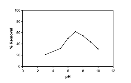
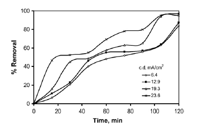
On how PH affects the removal efficiency of phenol through, the investigation revealed that optimal removal occurred at a PH value of 7 (Abdelwahab, Aminb and El-Ashtoukhy 713). This is shown in the graph in figure 2 in appendix B. On how operating time and current density affect the removal efficiency of phenol, the investigation revealed that optimal removal occurred after 2 hours and phenol removal increased with increase in current density (Abdelwahab, Aminb and El-Ashtoukhy 713). This is shown in the graph in figure 3 in appendix B.
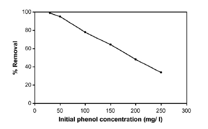
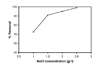
On how initial phenol concentration affects the removal efficiency of phenol the investigation revealed that removal efficiency declined as the initial concentration of phenol rose (Abdelwahab, Aminb and El-Ashtoukhy 714). This is shown in the graph in figure 4 in appendix B. On how electrolyte concentration affects the removal efficiency of phenol, the investigation revealed that optimal removal efficiency occurred when an electrolyte concentration of 2.5 g/l was used (Abdelwahab, Aminb and El-Ashtoukhy 714). This is shown in the graph in figure 5 in appendix B. The electrolyte used was sodium chloride (NaCl). On how anode thickness affects the removal efficiency of phenol, the investigation revealed that increasing anode thickness increased phenol removal efficiency (Abdelwahab, Aminb and El-Ashtoukhy 714). This is shown in the graph in figure 6 in appendix B. Increasing anode thickness was also seen to reduce energy and electrode consumption. The anode thickness is increased by adding aluminum screens.
Biological treatment
Biological treatment is another process (technology) used to treat ROW. According to Koytsoykos “the biological treatment of effluent water is based on the process in which a mixed population of micro-organisms uses as nutrients substances that contaminate the water” (12). Biological treatment is categorized as tertiary treatment of ROW. Koytsoykos further points out that “normally, aerobic micro-organisms obtain their oxygen from the free dissolved oxygen present in the effluent, but some organisms are able to obtain it from dissolved inorganic compounds when there is no free oxygen left: this is described as an anoxic process” (12).
Combining both aerobic and anoxic processes effectively reduces a significant portion of contaminants present in ROW. Aerobic process is particularly effective in removing the organic matter present in ROW whereas anoxic process is effective in the removal of the nitrogen present in ROW (Koytsoykos 12). An example of a biological treatment unit is the UASB bioreactor. The advantage of biological treatment systems is that they are environmental friendly. This because they treatment process does not use harmful reagents (Abdelwahab, Amin and El-Ashtoukhy 711). The disadvantage of biological treatment systems is that they cannot on their own treat ROW.
UASB is a biological refinery oily wastewater treatment process with proven efficiency. The technology that drives it has its basis on the fact that most of the toxic and stubborn organic compounds present in refinery oily wastewater are biodegradable under aerobic conditions (Gasim et al 174). The technology is implemented through systems known as UASB reactors and has three outstanding advantages (Gasim et al 174).
One advantage of this technology is that it is time effective since the reactors are designed to speed up anaerobic treatment and in effect reducing influent detention time. Another advantage of UASB technology is that it supports high loading rates of the wastewater thus for given unit of time a larger portion of influent can be processed. The other advantage of the technology is that it is cost saving as it eliminates significantly the amount of packaging material needed in the reclamation process. A shortcoming of this technology is that it is only effective in treating a single parameter of refinery oily wastewater, which is COD. As such, it cannot be used to comprehensively treat refinery oily wastewater. To deal with shortcoming, other treatment technologies have to be employed that treat the parameters left out. This implies more monetary spending for petroleum refineries that are conversely interested in treatment solutions that are cost saving (Peeters 3).
The efficiency of this technology is in how it removes COD in refinery oily wastewater. The efficiency of the UASB technology has been determined experimentally (Gasim et al 174). The influent for the experiment was wastewater from a petroleum refinery with a COD requirement of 7896 mg/L. The influent, at specific volumetric organic loading rates, was fed into two UASB bioreactors. The loading rates used were 0.58 Kg/m3.d, 0.89 Kg/m3.d, 1.21 Kg/m3.d and 2.04 Kg/m3.d. Two rates were used for each bioreactor and each rate used for 60 days.
The configuration of the two UASB bioreactors facilitated proper influent distribution and mixing. The effluent exiting the bioreactors did not come into contact with atmospheric air. The influent flow rate to the bioreactors was 1.4 L/d and HRT was kept at 40 hours. At the end of the experiment it was discovered that the bioreactors removed COD from the influent with satisfactory efficiency and that the highest efficiency attained corresponded with the 1.21 Kg/m3.d loading rate (Gasim et al, 177). Wastewater treated using UASB technology contains hazardous chemicals that limit its reuse to the refining process.
Membrane technology
Membrane technology is another biological water reclamation technology in use today. The technology is implemented using a membrane bioreactor, which consists of three units (Peeters 16). The first and second units are pre-treatment units whereas the third is a membrane based filtration unit. The first unit is an API or DAF separator for separating refinery oil and water. The second unit is an aeration basin for subjecting the remaining wastewater to aerobic treatment. This treatment is effective in biodegrading most of the toxic and stubborn organic compounds present in the wastewater (Gasim et al 174). The third unit is a membrane filtration unit which subjects the wastewater to hyper-filtration through reverse osmosis. This unit frees the wastewater of the remaining hazardous chemicals e.g. heavy metals.
An advantage of membrane technology is that it optimizes the biological treatment process of refinery oily wastewater by reducing reactor volumes and improving the removal mechanism of refractory organics (Peeters 18). Another advantage of membrane technology is that it properly integrates biological (aerobic) treatment and filtration (Peeters 18). The other advantage of membrane technology is that it exhibits improved resiliency, thus it is capable of handling low-, medium- or high-strength refinery oily waste water (Peeters 18). Water treated using membrane technology is of reusable quality. For instance, the refinery oily wastewater treated in PEMEX refinery, Mexico is reused by the refinery as a coolant and in the low-pressure boiler feed (Peeters 21). The refinery oily wastewater treatment plant has enabled the refinery to attain a water recycling efficiency of 70% as well cost savings (Peeters 20).
Ceramic membranes have been used at YPC to treat ROW that has been pre-treated through flocculation (Zhong, Sun and Wang 93). In the pilot experiment, though flocculation pre-treatment using 3530S reduced significantly the oil and COD content level the Chinese National Discharge Limit was not met (Zhong, Sun and Wang 93). This having been anticipated the ROW was additionally subjected to micro-filtration using Zirconia (Zr02)-based ceramic membranes developed by Nanjing University of Chemical and Technology. The ceramic membranes were microporous, had a thickness of 30 µm and a pore size of 0.2 µm (Zhong, Sun and Wang 94). The stainless steel cassette housing the membrane elements was 20cm long and both of its ends had rubber gaskets (Zhong, Sun and Wang 94).
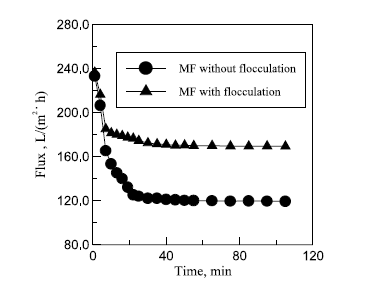
The results of combining flocculation and micro-filtration using Zirconia (Zr02)-based ceramic membrane are shown in table 6 in appendix A, table 7 in Appendix A and figure 7 in appendix B. Results in table 6 show that oil and COD content levels in the permeate meet the discharge limit of oil content less than 10 mg/l and COD content of 120 mg/l. The result in table 7 in appendix A shows an improvement of filtration flux after an hour of filtration. The explanation given by Zhong, Sun and Wang attributes this to flocculation, which they say increases the size of oil droplets, decreases the extent of pore plugging and increases the sedimentation layer void on the filtration membrane surface (96).
In membrane filtration it is imperative to know how operational conditions affect filtration flux, permeate quality and membrane fouling extent. Two operational conditions were studied in this case so as to determine the values at which these conditions should be set for optimal membrane filtration to be realized in the pilot industrial applications. The operational conditions studied were transmembrane pressure and cross-flow velocity (Zhong, Sun and Wang 96).
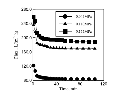
Figure 8 in appendix B shows the relationship that exists between transmembrane pressure and filtration flux. The graph shows that filtration flux increases with similar behaviour as transmembrane pressure is increased. The figures in table 8 in appendix A show how transmembrane pressure affects the permeate quality. Increased transmembrane pressure causes the oil content in the permeate to increase. The explanation for this provided by Zhong, Sun and Wang is that increasing pressure forces residual oil droplets through the membrane into the permeate (96). The discharge limit was exceeded when a pressure of 0.155 MPa was exerted. Increasing transmembrane pressure causes no significant change on the content level of COD in the permeate. On the basis of these findings a pressure level of 0.11MPa was recommended.
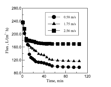
Figure 9 in appendix B shows the effect of cross-flow velocity on filtration flux. It seen that increasing cross-flow velocity increases filtration flux though not in a proportional manner. Zhong, Sun and Wang’s explanation for this is that increments in cross-flow velocity cause the membrane’s surface shear stress to increase and sedimentation layer height to decrease. Additional data also showed that as the flow progressed from a lamina flow to a turbulent flow filtration flux increased. As such, a turbulent flow favors increase of filtration flux. According to the figures in table 9 in appendix A, the quality of permeate increases as cross-flow velocity increases.
The possible explanation for this as provided by Zhong, Sun and Wang’s is that increments in cross-flow velocity caused a reduction of shear stress then an increase in the size of sedimentation layer void. These situations turn out of events caused more rejection of emulsified oil as well as other substrates. On the basis of these findings a cross-flow velocity of 2.56 m/s was recommended.
The main advantage of flocculation/ceramic membrane hybrid system is its improved separation performance that is characterized by high oil rejection, high membrane flux retention and reduced membrane fouling ( Zhong, Sun and Wang 94). The main disadvantage of this system is the high implementation cost since it is a combination of two ROW treatment processes. Another disadvantage of this system is that t employs the use 3530s that is harmful to the environment. The water reclaimed using this hybrid system is of high quality and therefore can be reused in the petroleum refining process and in municipal projects. In the refining process, it can be used as a coolant and as boiler feed water.
Chemical demulsifiers
During petroleum refining, it is common for water to mix with crude oil and thus forming either a water-in-oil or oil-in water emulsion. Refinery oily wastewater is an oil-in-water emulsion. To separate the both of these demulsifying (or desalting) chemicals can be used. The separation is done in one of three ways either by oil droplets flocculation, water dropping or water droplets coalescence (Roamex Limited). The speed at which chemical demulsifiers carry out their job is enhanced by operating conditions and the design of demulsification equipments (Roamex Limited). The choice of demulsifier to use in a particular case is determined using the bottle testing method. An advantage of this method is that it optimizes the performance of a demulsifier since its chemical formulation is enlightened by the test procedure.
Surfactants naturally occur in crude oil where one of their major functions is to prevent oil from mixing with another liquid such as water as this lessens its quality. They are usable in doing both forward (water-in-oil) and reverse (oil-in-water) demulsification (or emulsion breaking). Surfactants, when added to a liquid (e.g. refinery oily waste water) carry out demulsification through weakening the liquids surface and interfacial tension. Knowledge in surfactants has inspired the creation of a range of chemicals that offer advanced forward and reverse demulsification.
Amine is a chemical with the potential of use as a chemical demulsifier (Weatherford). Examples of amine-based demulsifiers are DB-904 and DB-951 (Weatherford). They have RSN values 12.5 and 10.0 respectively. Amine-based demulsifiers are particularly useful in treatment of oil-in-water emulsion or reverse demulsification. As such, they recommendable for use in the treatment of refinery oily wastewater. They are further effective in treating crude of mid-range gravity.
Amyl resin is a chemical that has the potential to be used as a chemical demulsifier (Weatherford). Examples of amyl-based demulsifiers are DB-954 and DB-955 (Weatherford). The chemical formulation of these demulsifiers makes them effective in demulsuifying
- mixed and asphaltenic crude oil and
- API crude oil of low to high gravity.
They have RSN values of 11.3 and 14.5 respectively.
Butyl resin is another chemical with the potential to be used as a chemical demulsifier (Weatherford). Examples of butyl resin-based demulsifiers are DB-942 and DB-945 (Weatherford). These demulsifiers are effective in demulsifying
- paraffinic and mixed crudes and
- API crudes of low to high gravity.
They RSN values are 9.5 and 9.0 respectively.
Nonyl resin is another chemical with the potential of being used as a chemical demulsifier (Weatherford). Nonyl resin-based chemical demulsifiers are the most commonly used. They are effective in demulsifying
- naphthenic crudes and
- API crudes of low to high gravity.
Examples of nonyl resin-based chemical demulsifiers are DB-934, DB-935, DB-946 and DB-947 (Weatherford). They RSN values are 15.0, 16.5, 10.5 and 13.5 respectively.
Esters and polyol esters are other chemicals with the potential of being used as chemical demulsifiers (Weatherford). An example of an ester-based chemical demulsifier is the Alpha 4068, which is a 60-65% active polymer (Weatherford). It is applied in crude oil treatment and dissaltation. To improve its performance it is recommended that it is dissolved in aromatic solvents such as naptha.xylene. Other examples of ester-based chemical demulsifiers are Alpha 4212, 4312 and 4531 (Weatherford). The DB-918 is an example of a poly-ester based chemical demulsifier (Weatherford). It has a RSN value of 7.5 and is effective in treating loose oil/water emulsions for which it gives out a distinct region of separation.
Polyol is another chemical with the potential of being used as a chemical demulsifier. Examples of polyol-based demulsifiers are the DB-911, DB-938, DB-961, DB-964 and DB-984. They RSN values are 10.8, 9.9, 13.3, 17.5 and 20.0 respectively. The DB-964 and DB-984 are used additionally in crude oil desalter formulations.
Sulfonate is another chemical with the potential of use as a chemical demulsifier. Examples of sulfonate-based chemical demulsifiers are Alpha 2618, 4153 and 4180. The Alpha 2618 contains an active sulfonate of ammonium that makes up 55-60% of its chemical composition. The Alpha 4153 contains an active sulfonate of isopropylamine that makes up 90-95% of its chemical composition. The Alpha 4180 contains an active sulfonate of amine that makes up 65-70% of its chemical position. To improve the performance of these demulsifiers, it is recommended that they be dissolved in alcohol or aromatic solvents such as naptha.xylene.
Fatty acids are other chemicals with the potential of being used as chemical demulsifiers. For instance, the Alpha 2619 is a chemical demulsifier that contains a 98-1005 active component of ethoxylated fatty oil. It is used in the formulation of surfactants. For better performance it is recommended that it be dissolved in water or in alcoholic or aromatic solvents.
Silicone polyether is another chemical with the potential of use as a chemical demulsifier. The effectiveness of silicone polyether demulsifiers is enhanced by silicones’ low surface tension, reduced temperature sensitivity, low toxicity and reduced cohesive energy (Dow Corning 1). Silicone polyether demulsifiers can be used on their own to demulsify water/oil emulsions or can be used together with other demulsifiers to improve their performance (Dow Corning 1). Silicone polyether demulsifiers have shown steady effectiveness in demulsifying crude of varying grades, e.g. low and high asphaltenic crude (Dow Corning 1). They, however, do not improve demulsification in other varieties of crude oil.
Benefits of silicone polyether demulsifiers are an increased rate of water dropping, improved interface definition, improved water quality and cost savings (Dow Corning 1). To save more on cost it is advisable to use Silicone polyether demulsifiers not as standalone demulsifiers but as performance enhancers of other emulsion breakers. To achieve the best results when using a silicone polyether demulsifiers , tests are undertaken that enlighten on the apt chemical and physical formulation (Dow Corning 2).
The tests involve experimentation with different types or ranges of silicone polyether demulsifiers on the same sample of crude oil and then determining which chemical and physical formulation gives the best results (Dow Corning 2). This only requires observation and use of logic. Once the best performing silicone polyether demulsifier is identified its dosage is configured in such a way that the desired level of performance is attainable. Examples of silicone polyether demulsifiers include those that make up Dow Corning’s ® DMx line of silicone polyethers. The line starts from Dow Corning® DM1 up to Dow Corning® DM6. Each series in the line captures silicone polyether demulsifiers that exhibit different properties such as viscosity and molecular weight.
Conclusion
To treat refinery oily waste water, this paper recommends a hybrid system. The reason for this choice is that individual technologies have been seen not to be able to sufficiently treat ROW to satisfactory levels. As standalone processes the above technologies are not even able to produce water that can be reused. As standalones they are, however, effective in removing individual contaminants present in ROW. Hybrid systems that are a combination of two or more these technologies have been seen to treat ROW to satisfactory levels. For instance, in the case of YPC flocculation was combined with ceramic membrane filtration (Zhong, Sun and Wang 93). This enabled the refinery to treat its ROW to levels that met the Chinese National Discharge limit (Zhong, Sun and Wang 93). Another reason for choosing a hybrid system is that these technologies are compatible.
These technologies can work together to achieve a common objective which is to produce high quality effluent. When working together none of the technologies reverses the efforts made by the others. The other reason for a hybrid system is to obtain a high quality effluent, which can have multiple reuse applications e.g. as a coolant in the refinery of as a source of fresh water. This has the potential to save on cost and to offset the high capital needed for implementing a hybrid system.
Works Cited
Abdelwahaba, Amin, and El-Ashtoukhy “Electrochemical removal of phenol from oil refinery wastewater” Journal of Hazardous Materials. 163 (2009): 711-716. Web.
Dow Corning, 2008, Crude oil demulsifiers. Web.
Gasim, Ahmed et al. “Treatment of Petroleum Refinery Wastewater by using UASB Reactors” International Journal of Chemical and Biological Engineering. 6 (2012): 174-177. Web.
Ismail, A. F. and Sudi Yuliwati, n.d., Membrane science and technology for wastewater reclamation. Web.
Koytsoykos, 2009, Oil refineries waste waters treatment available technologies. Web.
Lenntech. Re: Petrochemical company. 2012. Web.
Saudi Aramco, 2007, Saudi Aramco project development. Web.
Peeters, Jan. 2005. Membrane technology treating wastewater for reuse. Web.
Roamex Limited. Re: Demulsifiers. 2012. Web.
Weatherford. Re: emulsion breakers. 2012. Web.
Zhong, Sun, and Chely Wang. “Treatment of oily wastewater produced from refinery processes using flocculation and ceramic membrane filtration” Separation and Purification Technology. 32 (2003): 93-98. Web.
Appendix
Appendix A
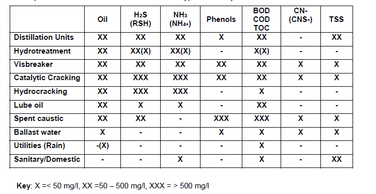
Table 2: Parameters of sample ROW from YPC’s refinery plant.


Appendix B
Key:
- DC power supply;
- anode;
- cathode;
- Reactor;
- Electrode gap;
- level of solution;
- water bath.
