Introduction
This is an industrial attachment report at the Saudi Arabian Amiantit fiberglass Industries (AFIL or Amiantit) during the coop session. The coop session is a seven-month period attachment that allows students to apply lessons learned in class to real-life situations.
The report presents AFIL, the fiberglass plant, types of products, processes involved in fiberglass production, and machinery for fiberglass production.
The Company
The Saudi Arabian Amiantit fiberglass Industries (AFIL) is “a company established in 1968 in Dammam in the Kingdom of Saudi Arabia” (Amiantit 1). Initially, Amiantit manufactured pipes for the local market. Since then, the company has grown and expanded its operation to global markets and diversified into other areas of pipe production. Amiantit core business activities consist of “manufacturing and trading in pipe systems, ownership and sales of pipe technologies, manufacturing and supplying of polymer products, providing water management consultancy and engineering services and producing polymer products for industries” (Amiantit 1). Currently, the company has several ranges of pipe products, and it offers complete solutions to customers’ fluid transfer requirements. These services meet the costs and technology needs of customers. Amiantit’s clients come from civil engineering, municipal, industrial, energy, and agricultural fields across the globe.
AFIL group has 30 production plants, six technology companies, four suppliers, and eight subsidiaries. The company has a presence in many countries around the world. AFIL also has branches to support its sales and service growth, which cater to customers in more than 70 countries and all over the world.
The company has its headquarter in Saudi Arabia where it participates in the Saudi Stock Exchange.
Amiantit has 30 pipe manufacturing plants in 18 countries. The company uses many materials in its products, such as “Glass Reinforced Plastic (GRP), Glass Reinforced Epoxy (GRE), thermoplastics, concrete, polymer concrete, and ductile iron” (Amiantit 2). The company also has other products, such as “pipes and accessories for water, sewage, hydropower, gas, oil services, construction, engineering, municipal, industrial, agricultural, and marine applications” (Amiantit 2).
Through technology, Amiantit has been able to advance “GRP, GRE, ductile iron, and polymer concrete” (Amiantit 4). In addition, AFIL also supplies rubber products for “sealing and air conditioning products, sizing and agents, coating materials to shield pipes and structures against decay and polyurethane products for pipes and tanks” (Amiantit 4).
Amiantit manufactures “fiberglass products, fiberglass reinforced plastic, sizing, and agent materials” (Amiantit 1).
Fiberglass plant
fiberglass entails a number of products prepared from individual glass fibers integrated into a range of different types. Fiberglass plant has massive machinery. These structures have various functions to serve processes involved in the production stages of fiberglass materials. The plant has dedicated areas for given stages to ensure that every composite and fiberglass work has adequate space. The plant has various compartments to ensure that there is no cross-contamination during the production of fiberglass. This ensures that the final product is of the best finish and quality. The company uses the most efficient processes in the production of fiberglass.
At the plant, a number of processes go on as a part of fiberglass production. However, the most widespread method of manufacturing reinforced plastics is open molding. Open molding is a common method of boat manufacturing. The procedure involves cleaning and coating the exterior with the wax in order to allow for simple separation of the final product from the mold before curing. After this stage, the gel coat follows, which has “a catalyst, unsaturated polyester resin, and pigments, which engineers apply on the mold” (Armatec p. 4). This becomes the outer and visible part of the product.
After the curing of the gel coat, engineers apply fiberglass-reinforcing material, which has catalyzed resin. Methods of applications vary, but some of them are chopper gun spray (spray coat) and hand layup. Periodically, engineers must clean these kits in order to get rid of elements of resin by using acetone before condensation of the resin (Mayer 7).
Hand layup
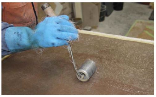
The hand layup process involves fiber reinforcement. In this stage, engineers place fiber reinforcement into the mold and then apply resin. This ensures that the result has a superior ratio of resin and high-quality control of fiberglass materials. Thus, the thicknesses of materials are at preferred ratios. The method is efficient for small to average amounts of fiberglass production, which is suitable for completed surfaces.
The agent in this process is normally in a form of wax or liquid. It ensures that the product remains clean from the mold. The process involved the application of resin to the surface. The resin consists of epoxy, two-part polyester, or vinyl. Engineers place sheets of fiberglass into the mold and apply additional resin by using either a roller or a brush. However, they must take precautions to ensure that the mold and resins conform to each other, and the process does not trap air between the mold and the fiberglass. The process may also involve the application of supplementary resin or extra sheets of fiberglass. Vacuum, hand pressure, or rollers are useful in “saturating resin, covering all layers, and removing air pockets” (McLellan and Shand 151).
This procedure must be adequately prompt to ensure that the work is over before the resin dries. However, high-temperature resins cannot cure unless warmed. In many processes, engineers wrap the work using a nylon sheet and then apply vacuum in order to eliminate air foams and then apply force on the fiberglass to achieve the desired physical features.

Spray Up
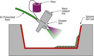
This stage involves the use of chopper gun to place chopped strand reinforcement and resin onto the mold. This is suitable for complex shapes. Spray-up is effective for large materials or several pieces of small items.
This procedure is also comparable to hand lay except that the use of resin and fiber materials on the mold changes. Spray up fabrication process is open. Engineers apply resin and reinforcement to the mold. The application of glass or resin may take place at the same time or separately. These materials come from a single chopper gun. Spray-up is useful in compressing the laminate. Additional foam or other core material may be useful with an additional spray-up layer to strengthen the core material. Finally, the stage involves curing, cooling, and removing from the mold.
Pultrusion Operation
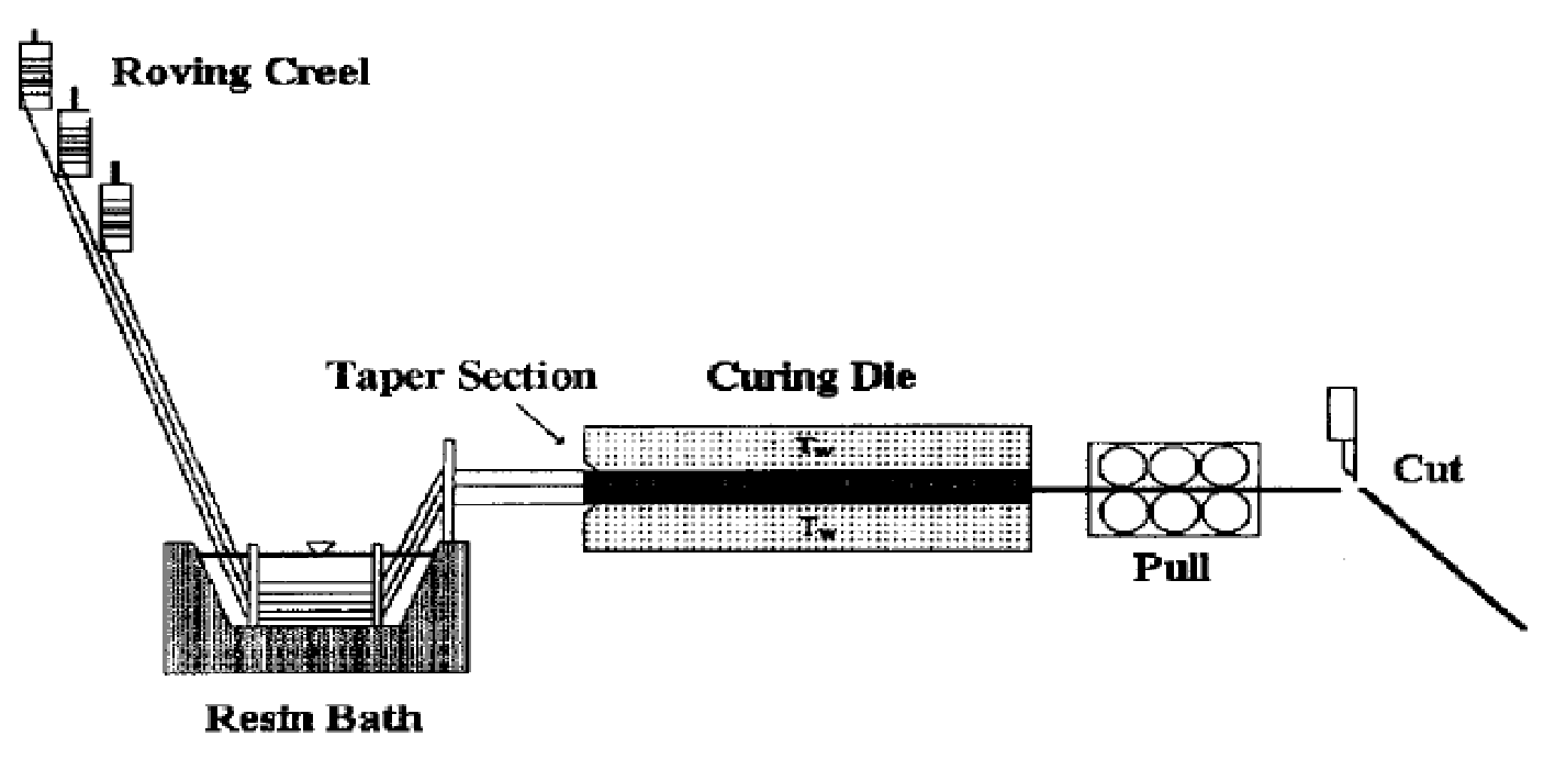
This method involves the production of strong and lightweight composite fiberglass materials. Engineers pull fiberglass materials from “spools by using a gadget that applies resin on them” (Moschiar, Reboredo and Vazquez 129). After the application, fiberglass materials go through heat treatment and are then cut into required sizes.
In pultrusion, engineers can produce different shapes and cross-sections of fiberglass materials. Pultrusion is a process in which the fiberglass materials go through machinery. The method uses a manual method of hand-pulling or a roller system. It differs from extrusion in which fiberglass materials go through the resin.
Resin Injection
Engineers place fiberglass for reinforcement in the mold. Resin injection is suitable for the high production of fiberglass materials or in cases in which two molded surfaces are necessary.
Injection molding is the process of producing fiberglass materials from both thermosetting and thermoplastic materials. Engineers inject these materials into the hot barrel, mix and force them into a mold system. As a result, the mixture goes into a molding system where it cools and becomes hard and takes the shape of the cavity.
After the designing process by an engineer or industrial designer, the engineer then molds materials by using a mold maker. mold maker is steel or aluminum material, which creates the desired parts. Injection molding is useful in the production of varieties of plastic products, from smallest to largest fiberglass plastics. Injection molding is the most popular method of manufacturing parts of fiberglass components. This is because it is ideal for the large production of parts of the same object. In addition, injection molding has the ability to use varieties of materials, reduce labor, and reduce works associated with finishing after molding. However, injection molding is expensive due to the molding of several parts with various designs.
The injection process involves feeding the granular plastic by gravity into a hot barrel. The screw-type plunger forces the granular forward into a heated chamber as it melts. Further, the plunger goes forward, forces the melted plastic through the plunger, and allows the melted plastic into the mold opening. The mold is always cold in order to allow the melted plastic to cool as soon as it reaches the chamber.
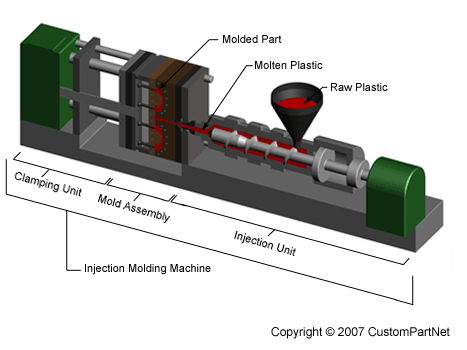
This process of injection molding involves the molding cycle. The process starts when the form stops, and then the shot follows through to the mold opening. As soon as the opening is full, the system must keep up a supporting pressure in order to balance the contraction of the melted plastic. After this stage, the bolt turns in order to allow the content into the subsequent space. This process makes the bolt drawback as the next injection moves forward. As soon as the part is cold, the mold releases and discharges the content.
The resin injection also has processes, which can create technical challenges. The best conditions are necessary for high-quality products because they influence the quality of the final fiberglass materials. Problems usually arise from plastics contaminated with scrap. Therefore, engineers must make sure that studies for process optimization are reliable, and that process monitoring is effective. Engineers normally use Industrial CT Scanning for both external and internal inspection of materials and porosity of the system.
The molding tolerance is “the provision of an allowance for a digression of plastics in measurements, weights, angles, shapes, thickness, and others” (Aird 89). In order to enhance control of setting tolerances, engineers must set both minimum and maximum limits of measurements of the thickness. However, this depends on the process applied.
Table 1: molding Tolerance Allowance
3.5 Vacuum Bag
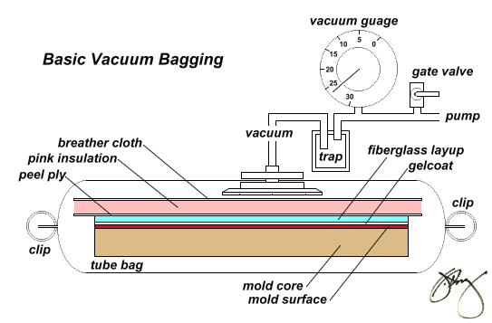
This is usually for specialized applications in the manufacturing of fiberglass materials with carbon. Vacuum bagging removes surplus resin and absorbs it into cloth. This gives fiberglass material the best strength with lightweight ratios. After every process, engineers must discard vacuum bagging materials.
Resin Infusion
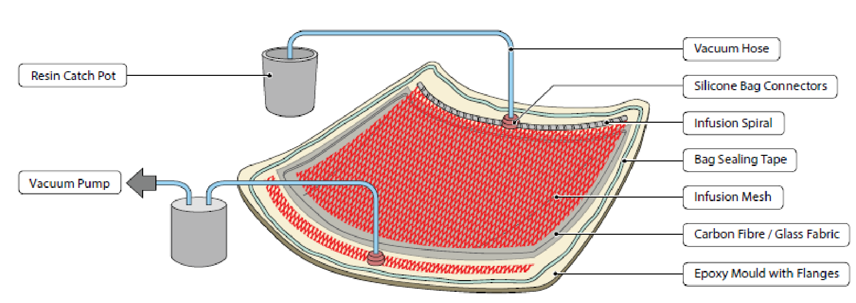
Resin infusion is “a state-of-the-art technology in which engineers introduce resin to the mold through a vacuum delivery system as they manage both lightweight and strength ratios” (Armatec pp. 1-45). Resin infusion is a complicated method of producing high-standard fiberglass materials on complicated or large molds. It is usually suitable for the production of carbon fiberglass materials. Engineers apply this technology in cases where the open layup method is not effective, especially in small and detailed materials.
Engineers place fiberglass for reinforcement into a dry mold (mold without resin) and then enfold the reinforcement with bagging materials like peel ply, bagging film, or infusion mesh. After this process, they subject the material to vacuum pressure by using a composite vacuum pump. This pressure results in the elimination of air from the bag. Once compression of the reinforcement has occurred under atmospheric pressure, engineers then introduce liquid epoxy resin that contains hardener, which then infuses the material under the vacuum. As soon as the mixture is complete, engineers stop the flow of the resin and then leave the resin to dry under a certain space pressure.
A well-performed resin infusion process can result in strong materials with an incredible quality of appearance. Mixtures of a vacuum pressure together with the arrangement of vacuum elements like infusion mesh and peel ply ensure that the fiberglass material has absorbed resin. Resin is optimum in order to enhance the reinforcement ratio. However, the process ensures that the product is not resin-rich.
Resin infusion helps in the removal of some challenges associated with blight wet-lay composites. These may include air voids from bridged tight corners and air bubbles resulting from air traps contained by the laminate.
The feature of epoxy infusion resin can create strong materials with lightweight, which are better than materials from pre-impregnated reinforcement processes.
Products
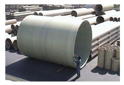
Amiantit has several fiberglass pipes. There are two main categories of fiberglass-based on their geometry. These are short or discontinuous fiberglass and continuous fiberglass. Continuous fiberglass materials are useful in textiles and yarns while short fiberglass is appropriate for blankets and boards for insulation and filtration.
fiberglass textiles are mainly appropriate for formed and plastic-coated materials as supporting materials. On the other hand, fiberglass wool is mainly suitable for thermal insulation. This type of fiberglass material is generally found in “boats, submarines, vehicle engine compartments and body panel liners, furnaces and air conditioning systems, ceiling panels, and architectural detachments” (Aird 102). Therefore, we have to note that fiberglass materials can be applicable in many areas and serve specific purposes. For instance, we have “Type E for electrical insulation tapes, Type C for chemical in order to provide a superior resistance to acid and Type T that is suitable for thermal insulation” (Armatec p. 8). Thus, commercial usages of fiberglass materials have gained attention over the past decades. This explains why Amiantit has several ranges of fiberglass pipes for various purposes. Research and development (R&D) has resulted in massive production of fiberglass for industrial and other usages (Aird 86).
Amiantit has developed low-cost, fine, and flexible fiberglass materials by using molten glass. Some of its products are in the below table.
Table 2: fiberglass Products, Ranges, and Options
Chopped Strand Mat (CSM)
CSM is a type of reinforcement applied in fiberglass. CSM has randomly laid glass fibers across the entire mat and is holding them together with a binder. The hand layup technique is the appropriate method of processing CSM. Engineers place sheets of materials onto a mold and then brush with the resin.
Binders melt in the resin. As a result, the material simply matches various shapes when wet. The resin then cures resulting in a hardened product. Workers can then retrieve the material from the mold and perform finishing on it. CSM enables the material to acquire isotropic qualities.
Pipes
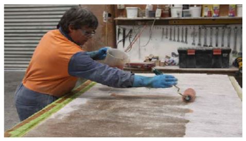
The company manufactures all types of glass-reinforced epoxy pipe systems and different types of fittings. These pipes are mainly of “standard measurements and they conform to the ASTM D-2996 specification” (Amiantit 6). Amiantit pipes also meet ISO 14692 and API requirements. In addition, pipes and fittings have to “meet NSF certification for safe drinking water use and FM (factory mutual) approval for fire protection” (Amiantit 6).
Fittings and accessories
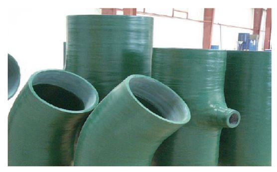
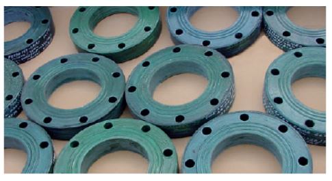
Amiantit provides various filaments, fittings, and flanges. Some of the standard fittings and flanges include
- 90° Elbows
- Couplings
- 45° Elbows
- 45° Laterals
- Equal tees
- Nipples
- Reducers
- Flanges
Spools
The company provides prefabricated spools on requests.
Joining Systems
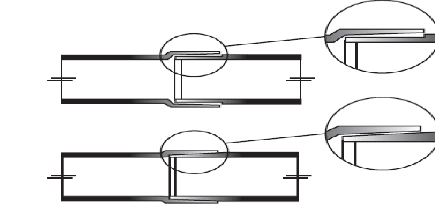
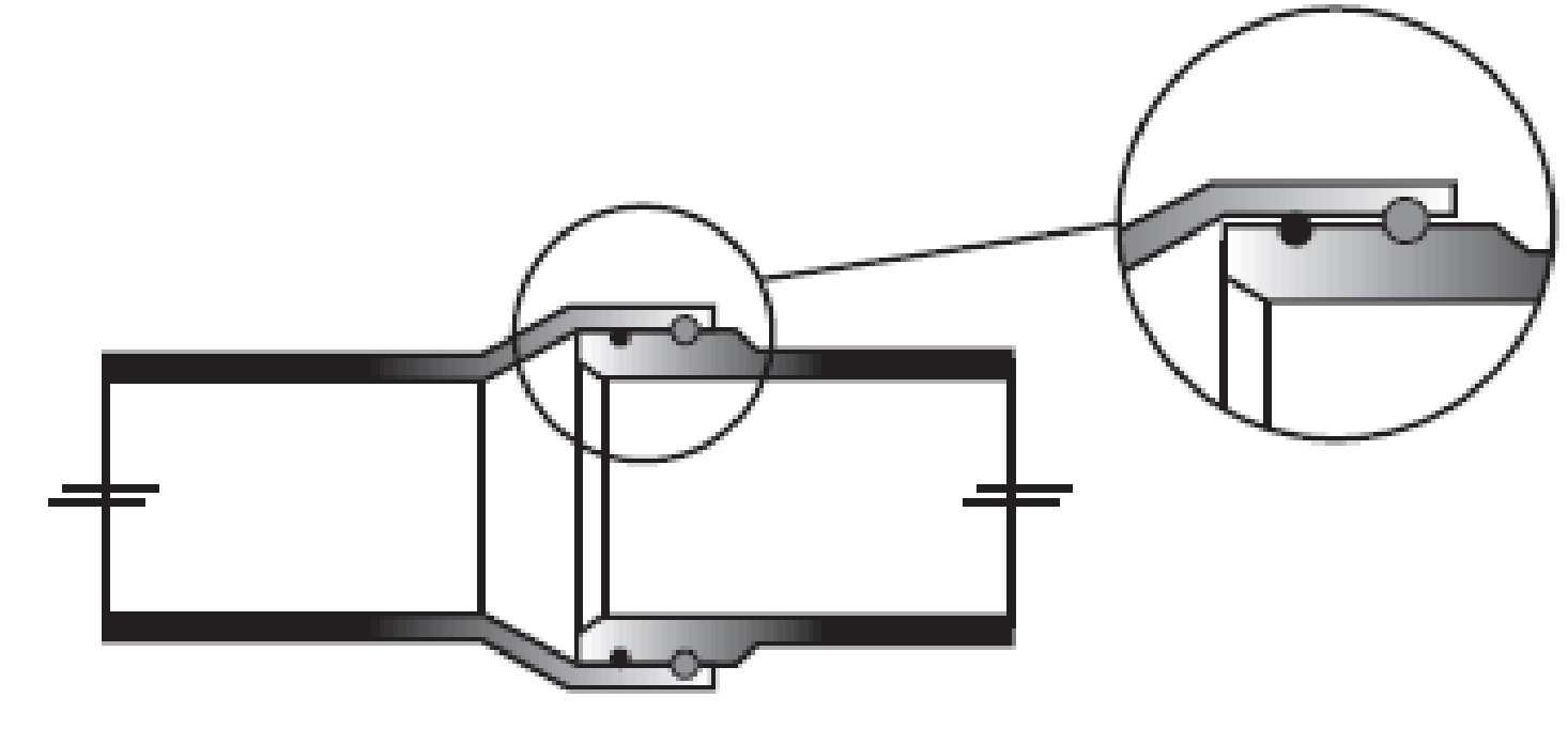
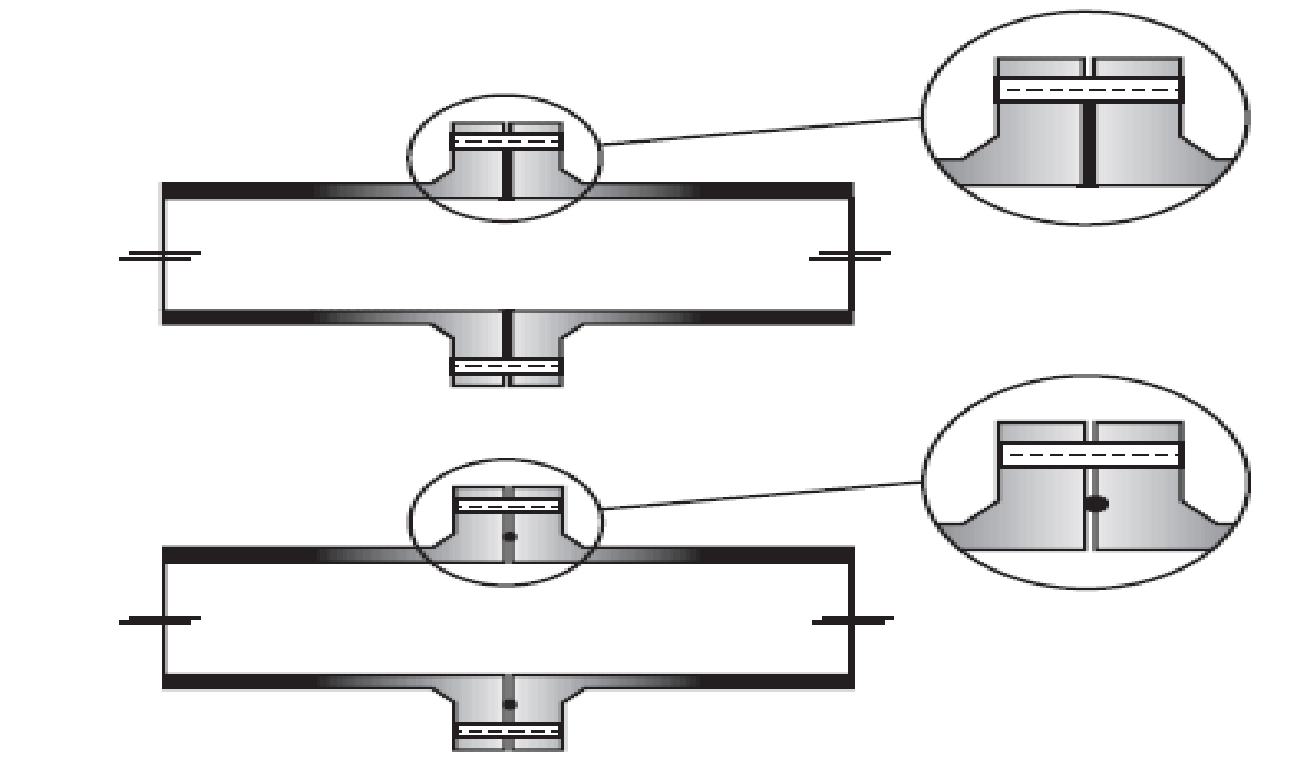
Amiantit has adhesive joints, flange joints, and mechanical joints.
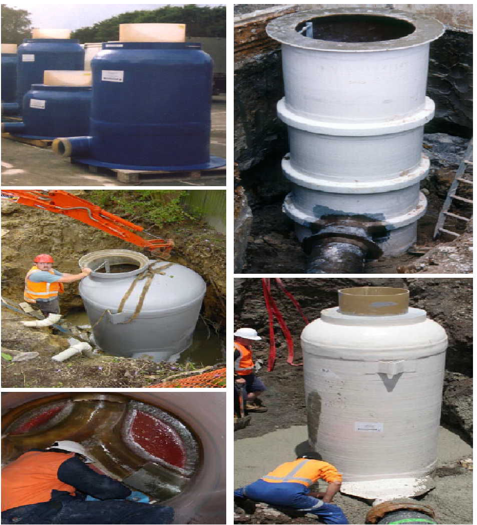
Fiberglass Raw Materials
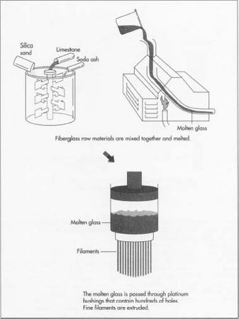
Fiberglass raw materials consist of “manufactured chemicals and natural minerals” (Aird 98). These are mainly silica sand, soda ash, and limestone. Other raw materials consist of “borax, calcined alumina, magnesite, feldspar, nepheline syenite, and kaolin clay” (Aird 98). Silica sand serves as “the glass former while soda ash and limestone control melting temperatures” (Aird 98). Borax is useful in enhancing chemical resistance properties. Cullet (waste glass) is also a part of the raw materials. Engineers must ensure that raw materials are of exact quantities and mix them prior to heating them into a glass form.
There are large furnaces that melt the mixture of silicon and sand and other chemicals in order to create the liquid. The liquid then goes through small holes. The company uses platinum bushing with three-thousand holes in order to manufacture 3,000 fiberglass threads in a single process. The processes result in tiny fibers. Engineers then work on these fibers in order to develop fiberglass yarn or chop them into a mat.
Fiberglass Production
- GRP (Glass fiber Reinforced Plastic) pipe systems
- GRE (Glass fiber Reinforced Epoxy) Pipe systems
Amiantit has GRE and GRP pipes and fittings. These pipes are from high-strength fiberglass (E-glass) and amine cured epoxy resin. These materials ensure that the product has optimal strength and is lightweight. The plant has several machines, which control various many fiber production processes. Combinations of these procedures with the new tools ensure that the final product is of the best standard. There are also provisions of the extra liner of 0.5 mm depending on the application of the material.
There is an optional resin-rich liner, which has “C-glass or C-veil with the same resin in pipes used in walls” (Amiantit 7). These pipes are also compatible with steel pipes. Amiantit manufactures various ranges of fittings and pipes to show that various designs and procedures are possible.
Amiantit offers GRE pipes with various advantages in a single product. For instance, GRE pipes are corrosive resistant with corrosion-free materials. This implies that such piping systems do not require “both internal and external coatings, cathodic protection, chemical inhibitors, and corrosion provisions” (Amiantit 7). The pipes also do not have rust particles, which extend their lifetime.
The pipes also reduce energy loss due to low thermal qualities. This implies that insulation may not be necessary in most cases. fiberglass pipes have smooth inside surfaces. This ensures a Hazen Williams factor of 150. This provides an opportunity for small pipe diameter for any amount of fluid. This reduces the cost of piping systems. In addition, fiberglass pipes eliminate “the accumulation of resin, paraffin, and asphalt found in the crude oil transmission systems” (Amiantit 7). This happens due to low internal friction.
Amiantit uses high precision winding technology in order to achieve a balance between wall thickness and strength ratios. Thus, the result is a pipe with a low weight per pressure category. There are fiberglass pipes for “both above and underground applications” (Amiantit 1). According to Amiantit, the lifecycle of a fiberglass pipe exceeds stainless steel.
Processes of Manufacturing fiberglass Pipes
Melting
Engineers must ensure “precise control of the temperature in order to guarantee a smooth and steady flow of the molten glass” (McLellan and Shand 178). The temperature of the molten glass must be in the range of 25000 C. This ensures that glass turns into the fiber. Once the glass has melted, it then goes to “the forming chamber through a channel at the end of the furnace” (McLellan and Shand 178).
Formation of fibers
There are many processes and procedures involved in the formation of fibers. However, these processes and procedures depend on the type of fiber required. Textile fibers for plastics and pipes may come directly from the furnace. In some cases, the molten glass may first pass through the system where it forms glass granite. These forms provide opportunities for checking of the glass for any foreign substance. In either process of a direct melt or a marble inspection process, engineers use “electrically heated bushings or spinnerets to feed the system” (McLellan and Shand 178). Spinneret consists of alloy or platinum with extremely fine orifices. At this stage, the glass fiber goes through holes and comes out as fine yarn.
Constant fiber formation process
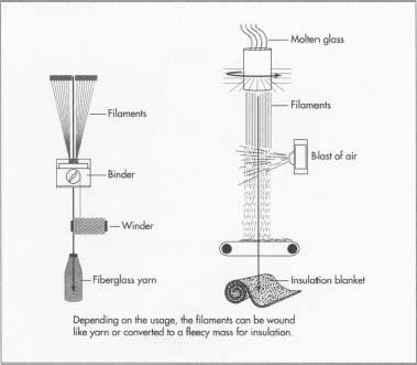
Engineers can manufacture a long fiber by using a constant fiber formation process. The high-speed winder traps several strands of molten glass as “the molten glass flows into the bushing” (McLellan and Shand 188). The winder covers three kilometers in a single minute. This speed exceeds the rate of the bushing.
The force draws out threads in a molten state and forms several threads of similar measurements like the bushing. After this process, engineers apply a chemical binder. This helps to keep the fiber intact during later stages. The subsequent step involves winding the fiber onto tubes. In this stage, engineers can twist and ply the molten glass into yarn.
Stapling fiber formation process
This is another method of fiber formation. When the molten glass goes through the bushing, a rushing air quickly cools the fiber. At the same time, this jet of air breaks the molten glass into different lengths, which range from eight to 38 centimeters. These materials then go through a spray of oil into a spinning drum where they form lean webs. The system draws “the web from the drum and pulls it into a long thread of loosely held fibers” (Todd 225).
Chopped fiber
In some cases, engineers may create the molten glass into short lengths by chopping them. In this process, they mount the filament on “a creel (bobbins) and pull it through a machine that chops it into short lengths” (Todd 226). Curing takes place in an oven where they roll the mat. This is where engineers create various materials of various thicknesses and weights.
Glass wool
The spinner process creates grass wool. During this process, molten glass from the furnace goes into a cylinder with little holes. The horizontal strand of glass goes out through the holes as the cylinder spins at a high speed as “the cylinder spins at a high-speed” (Todd 226). The hot jet of air or gas then changes the molten glass into the fiber. At this stage, these materials fall on a conveyor in which they interweave with each other and form a mass of fiber. The product is suitable for insulation or engineers can still spray the wool with a binder, then constrict it to desired thickness, and take it to a curing process through an oven. The heat controls the binder. As a result, it may create a rigid, loose, or flexible butt.
Coatings
Apart from binders, there are also other necessary coatings for fiberglass pipes. Engineers apply lubricant in order to eliminate fiber abrasion. They can directly spray or add lubricants with binders. Anti-static elements are also useful for fiberglass insulation. Engineers apply this composition during the cooling stage. The cooling gas drives the anti-static chemicals into the fiber mat. This chemical usually has a material that reduces the production of static electricity and material that acts as a stabilizer and corrosion inhibitor.
Sizing refers to any coating used on textile fibers during forming processes. It may contain lubricants, coupling materials, binders, or a combination of all these agents. Coupling agents are applicable in threads, which reinforce plastics. They strengthen links in the reinforced materials.
In some cases, finishing processes are useful for removing coating or putting additional coating. However, for plastic reinforcement, engineers may use “heat or chemicals in order to remove sizing, and then apply coupling agent” (Todd 216). The decorative application requires heating of the fabric in order to “eradicate sizing and introduce the weave” (Todd 216). Engineers can then apply dye base coating before printing or drying processes.
Forming into shapes
fiberglass pipe insulation undergoes a “winding process onto rod-like mandrels from the forming chambers before the curing process” (Todd 216). The resulting mold then goes for curing in an oven. The length is usually 91 cm or less. molds have specified lengths as required. In case facing is necessary, materials undergo a facing process before packaging for shipment.
Machines
Winding machine
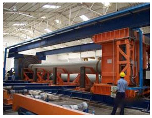
Winding machine consists of seven disks, shaft complete, 80 aluminum beams, steel band, chopper, and a receiver unit. A simple version of a winding machine usually consists of two axes in motion. These include trap travel and a revolving mandrel. For the production of pipes, two axes machines are the most appropriate. In cases of productions of pressure items such as LPG, it is appropriate to “use a four-axis winding machine” (Todd 220). The four-axis machine also has a “cross-feed system that is vertical to the carriage travel and the revolving fiber receiver head that is at the cross-feed axis” (Todd 220). Engineers can use this system to stop the fiber thread twisting and create materials of various lengths.
A filament winding system of fabrication allows engineers to produce composite fiberglass materials of cylindrical structures. This process encompasses the winding of fiber under a changing quantity over the mandrel. The carriage moves as the mandrel rotates. This produces fiber of the desired mold. Under this process, engineers can produce both glass and carbon fiber, which they coat with artificial resin as the winding process proceeds. After the curing process, the machine delivers a final hollow product.
Winding machines with several axes are useful in the advanced production of fiberglass materials. The modern winding machines with more than two axes have computer-controlled systems. At the same time, a two-axis machine may have both computer and manual systems of controls.
The modern computer-managed winding machine has special software that creates both the winding patterns and paths for the machine. The software may come with the machine or engineers may obtain it separately from specialized stores.
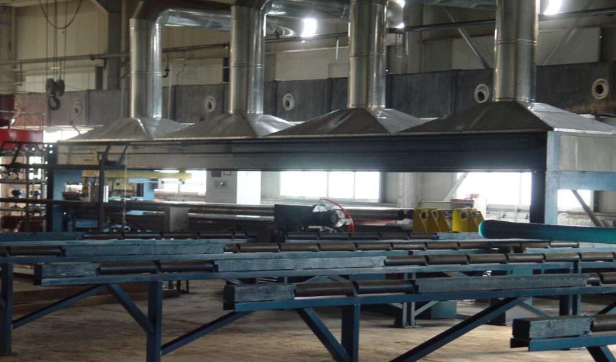
Calibration Machine
Calibration machine receives the produced pipes for testing. It consists of a calibration drum, cutting systems, and a lifting table.
Calibration services on pipes are useful for controlling and adjusting pipes’ accuracy in terms of measurements. Accuracy is fundamental for the effective function of precision and measurement instruments and devices in the pipes manufacturing industry. Therefore, the constant calibration in fiberglass production is a necessary part of preserving the required accuracy and quality standards.
The calibration machine must measure the behavior of pipes through measuring instruments. This allows engineers to gauge the specifications of pipes against the standard measurements. This process allows engineers to perform needed adjustments on products until they meet the specified requirements.
Most instruments in the fiberglass industry must maintain a given unit of measurement to enable them to perform well. Still, devices that monitor changes in other instruments also need regular calibration. For instance, in fiberglass production, the industrial-scale monitor’s measurements of pipes. However, the machine undergoes wear and losses its accuracy over time. Thus, it also requires calibration. Devices for producing mass and small pieces of fiberglass products also need calibration. This is necessary for the accuracy required in piping products.
In pipes, AFIL must ensure that all pipes and other products have the right strain, pressure, humidity, temperature, corrosion, mass, and thickness measurement. The company must rely on defined and specified standards as national and international bodies, such as ISO, API, the ASTM D-2996, and FM specifications. These standards are essential for home and worldwide trade and make sure that there are accurate products within the industry. Therefore, calibrating services are mandatory processes that engineers must ensure that all pipes undergo.
Calibration measurements are effective ways of ensuring quality products in terms of specifications. However, it may be difficult to identify all factors, which influence the quality of a product as well as the calibration process. Thus, engineers must account for such uncertainties during calibration processes. This implies that errors may occur even with the most accurate calibration machines. In this process, engineers must know exactly what to do in order to produce similar products, which meet established standards. Therefore, a calibration machine is a high-quality control system that is necessary for precision in the measurement of all pipes.
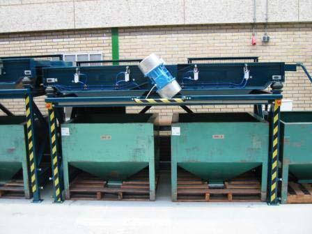
Hydro test Machine
This machine tests for leaks and strengths in the produced pipes. It consists of two end seals and a water pump.
Engineers use a hydrostatic test in pressure products like pipes, fuel tanks, boilers, pipelines, and gas cylinders in order to establish their strengths and availability of leaks. The testing process involves pumping water into the pipe. Dyed water is appropriate for testing leaks for ease of identification. They pressurize the pipe to a given pressure and then test for pressure defects. They can then identify the specific location that is responsible for pressure loss. At the same time, they can test for the strength of the pipe by observing and measuring any stable deformation on the pipe.
AFIL uses hydrostatic testing in all its pipes and other pressure products. The test is necessary to ensure that pipes are safe and retain their durability qualities. Therefore, new pipes must undergo a hydrostatic test as an initial qualification process. Pipes then undergo a re-qualification process at regular intervals under a procedure known as a modified hydrostatic test. Pipes for gas, pump stations, storage tanks and others require pressure testing because of the danger of explosions in case they fail pressure standards.
Engineers must perform hydrostatic tests under constraints of the industry, customers, or as the law requires. During this procedure, they fill the vessel with water or oil because of their incompressible qualities and then inspect for leaks or changes in shapes. They may dye the fluid in order to facilitate the detection of leaks. During testing, the test pressure must exceed the normal pressure of the vessel as a precaution for the safety margin. The margin can range from 50 percent to 60 percent above the normal vessel pressure. However, this depends on the industry specifications and regulations that apply based on the usage of the material.
Conclusion
This coop session was a well-thought-out work experience in a professional and a global company during which we applied and acquired knowledge, skills, and experience. The session at AFIL involved the use of learned skills and knowledge in the company in fiberglass pipes production. The process provided valuable challenges to the student during the interaction with various processes involved in fiberglass production. It helped in assessments of the experience involved and the learner’s knowledge in a manner it applies to the coop session. Apart from these insights, the coop session enabled the learner to explore career opportunities in fiberglass production, acquire new skills, get work experience, develop professional networks, and identify with workplace expectations and procedural requirements.
During the 1990s and beyond, the fiberglass industry experienced challenges that needed advanced approaches. Consequently, leading players like AFIL embarked on technology in order to solve some challenges in the production of various materials of fiberglass.
During the manufacturing of fiberglass materials, materials undergo several processes in order to achieve the desired standards and qualities. These processes involve mixing of the batch, melting of the glass from the bushing, and then a strand of fiber comes out of the machine for curing processes into the final product.
Engineers must analyze fiberglass samples for the presence of impurities, chemical composition, and any flawed processes. The material must undergo many tests in order to determine the particle size circulation. The final material must also go through thickness measurements as required in various standards. Any change in the thickness of the fiberglass implies that the material does not meet quality standards.
AFIL relies on several standardized procedures of tests and measurements, adjustments and optimization of products in order to ensure their standards. At the same time, AFIL also focuses on other features like corrosion, pressure, and temperature resistance. It must also control the strength and lightweight ratios of the product. It achieves features by controlling production variables, such as “length, thickness, binder content, and density” (Mayer 8).
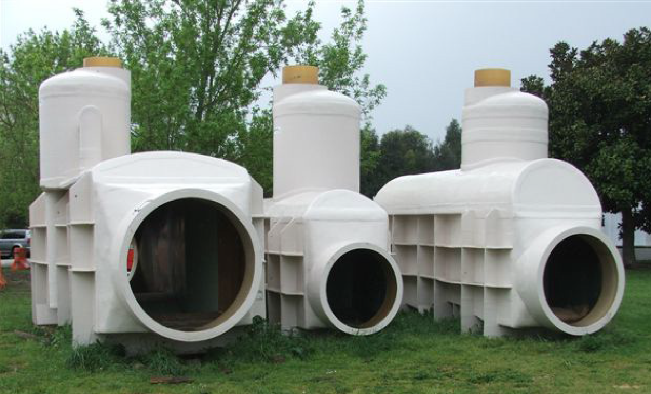
fiberglass remains one of the most versatile materials. It is strong, lightweight, and resistant to corrosion and extreme weather. Thus, the material has several applications due to its diverse nature. AFIL designs produces and installs fiberglass materials, such as “pipes, ducts, fittings, vessels, scrubbing plant, process vessels, storage tanks, pump stations, water tanks, and others” (Amiantit 2). These products include “GRP and FRP of high thermoplastics specifications for extreme conditions” (Amiantit 2). In some cases, AFIL applies fiberglass products on rubber lining, concrete, and steel installations in order to act as corrosion protectors.
References
Aird, Forbes. Fiberglass & Composite Materials: An Enthusiast’s Guide to High-Performance Non-Metallic Materials for Automotive Racing and Marine Use. New York: Penguin, 1996. Print.
Amiantit. 2012. Web.
Armatec. fiberglass Products for Drainage Systems. New Zealand: Armatec, 2010. Print.
Mayer, Rayner. Design with reinforced plastics. London: Springer, 1993. Print.
McLellan, George and Errol Shand. Glass Engineering Handbook. New York: McGraw- Hill, 1984. Print.
Moschiar, Maris, Maria Reboredo and Analia Vazquez. “Pultrusion Processing.” Composites Science and Technology, 17, 3 (1996): 126-160. Print.
Todd, Robert. Manufacturing Processes Reference Guide. New York: Industrial Press, 1994. Print.