Introduction
In the contemporary world, the utilization of metal stampings in readymade products has realized significant augmentation. For instance, consumer and industrial goods with sheet metal portions range from automobile and truck bodies to computer hardware. Within the continuum are products such as airplanes bodies, railway cars, farmhouse and building tools, machineries as well as office fixtures and fittings.
The examples provided are conspicuous since sheet-metal form part of their exteriors. However, most of their internal components are also made of sheet metal. According to a survey conducted in the US, over 100,000 metal stampings could be found in the average American home during 1980s. The commercial importance of sheet metalworking is significant. The three major categories of sheet metal processes are cutting, bending, and drawing. In order to isolate outsized sheets into smaller pieces and to shape a portion boundary, cutting is often employed. Additionally, cutting is invaluable in creating holes in portion bending. On the other hand, the construction of sheet metal parts into the requisite shape involves drawing. The study emphasizes on the procedures involved in drawing.
Specifically, sheet metal stamping process, which is a well-designed process, is important than online SPC controls. Essentially, the SPC controls are the most famous and widely used tools in industries. The key concept here is the usage of control limits instead of specification limits denoted in the design drawing or manufacturing instruction card. Essentially, the use of traditional SPC charts in observing the process often leads to deficient adjustability in the process variable input settings of a sheet metal stamping procedure.
Besides, when conventional SPC charts are utilized, out-of-control signals often designate the encounter of the process mean shift. In such situations, bending the mean response in an out-of-control condition is difficult. In principle, disregarding the signals is of greater significance. As such, additional expense might be incurred due to augmented service costs under warranty. Most importantly, the possibility of reduced sales is imminent due to the loss of market share resulting from customer dissatisfaction.
Background research (Finite Element Method and its application in sheet metal forming)
The availability of a system paradigm that associates input to output is essential in comprehending the consequences of method reservations on product value. In this regard, numerical simulation anchored on finite element procedure is invaluable in interrelating output and input in manufacturing processes. Actually, a number of contemporary productions continues to embrace and utilize the Finite Element Method (FEM) in industrial procedures including forging, rolling and stamping. Further, manufacturing processes also use FEM in injection modelling, die-casting and machining. Moreover, in terms of forging/rolling simulations, DEFORM and FORGE3 are two major FEM packages utilized. Besides, in terms of stamping, PAM-STAMP and LS-DYNA are dominant. In addition, for injection moulding, MOLDFLOW is prominent. Furthermore, in die-casting, PROCAST is central. In machining, DEFORM has developed a dedicated module to simulate the chip formulation and breakage.
Sheet Metal forming
Thin and plain portions of steel that are not more than six millimetres are often referred to as sheet metal. For instance, metals including brass, aluminium, tin, copper, cold rolled steel and nickel as well as titanium can be created into sheet metal. Besides, the sheet metal creating configuration incorporates input parameters including the blank, tooling and tool-material edge surroundings. Moreover, the mechanisms of plastic bending, tools cast-off as well as features of the ultimate merchandise are also incorporated in the sheet metal forming system. Further, the plant setting in which the procedure is accompanied is also part of the sheet metal forming arrangement.
In the design, control and optimization of sheet forming processes, competencies in various fields are essential. For example, diagnostic acquaintance in metal flow is critical. Additionally, the pressures combined with technical information concerning lubrication and material handlings as well as forming equipment are necessary. Moreover, die design and manufacturing are also critical in this process.
The mechanics of deformation is a significant part of the sheet metal forming structure since it enhances the determination of the stream of metal flow and the ease of obtaining the preferred geometry. Further, the mechanics of deformation enhances the production of the anticipated mechanical attributes of the produced part.
Displacement, strains, strain-rates and velocities are critical in the explanations of the state of bending in a plastically deforming metal range. Conversely, stretching, drawing, and bending are the basic metal sheet forming devices. Additionally, the definition of the constraints in sheet metal forming is anchored on the incidence of imperfections including creases and breakages in the blank.
Basis of Finite Element Method
The concept of finite element procedure may be dated back to 1943 when Courant approximated the warping function linearly in each of an assemblage of triangular elements to the St. Venant torsion problem and proceeded to formulate the problem using the principle of minimum potential energy. Several investigators who tried to obtain the approximate solutions to certain boundary-value problems later used similar ideas. Clough is the first person to introduce the term “finite elements”.
Discretization forms the foundation of the finite element method. Actually, the processes involved in the construction of the finite element model encompass the documentation of a number of finite points in the realm of the function. Thereafter, the values of the function and derivatives are quantified at the points described as nodal points. More importantly, finite elements are critical representatives of the function domains collections. Subsequently, the elements of the domain are grouped on the peripheries. Finally, averaging of the function takes place locally by continuous functions inside every component. During the approximation, elements are defined exclusively in terms of the nodal-point values concomitant with an actual component.
The path to the solution of a finite element problem consists of five specific steps:
- Identification of the problem.
- Definition of the element.
- Establishment of the element equation.
- Assemblage of element equation.
- Numerical solution of the global equations.
Application of Finite Element Method in Sheet Metal Forming
Over the past two decades, the utilization of finite (FEM) expertise in stamping applications has continued to realize augmented levels. Actually, regarding the account of virtual stamping, the period afore 1990, which was a pre-mechanization, marked the beginning of computer use to comprehend the requirements needed to advance the forming procedure. The major focus of the pre-mechanization era encompassed the methodologies including expert system and knowledge-based procedures. Most importantly, the formation of simulation through the utilization of FEM in stamping correlated complications was a major achievement in the pre-mechanization epoch.
The utilization of elastic-plastic method offers comprehensive explanations of stretch-forming and deep-drawing problems. Principally, the approach takes into consideration that the interaction problems at the blank receptacle, die and profile as well as punch head, were obtained by Wifi. Based on the nonlinear theory of membrane shells, Wang and Budiansky came up with a process used to compute the deformations realized in stamping of sheet metal through randomly moulded punches along with dies. Besides, Onate and Zienkiewicz developed a finite-element design utilizing the leaning on the viscoelastic flow theory for continuum problems.
According to Onate and Zienkiewicz, the theory was applied to handle thin shells. Further, Toh and Kobayashi used then finite-element method centred on the membrane theory to scrutinize sheet-metal developing procedures. The sheet-metal developing procedure can be either axially symmetric or non-symmetric. In the finite-element model, the attributes of the inelastic-plastic material along with the usual anisotropy of the sheet metal are always incorporated. Moreover, the determinate deformation processes that take place in the sheet-forming process are also included.
Indeed, stamping simulation software is critical in enhancing strain predictions as well as the institution of stamping expertise. The software provides answers concerning the reduction of outlays and lead-time of several domains. Actually, the stamping process is affected by the part geometry and the die run-off design as well as the materials’ selection. Additionally, the manufacturing hardware and process in addition to quality control also influence the stamping process.
Forming limit curves
Forming limit curves are significant advancements for examining the formability of sheet metals. Besides, in the curve, the onset of visible and localized necking in a bowed sheet is where the surface strains are strategized. Further, the locus of strain permutations yielding failures in an actual forming operation are also drawn on the onset of visible and localized necking in a bowed sheet. The construction of forming limit curves utilizes experimental methods. Besides, the strain state is associated with the formability of the curve. In principle, the blend of the three principal strains ε1, ε2 and ε3 are known as the strain state. Normally, the supposition is that the summation of the principal strains is zero. In fact, the specification of the strain state involves only two principal strains. As such, ε1 and ε2 are normally utilized. Moreover, the expression of the ratio between the principal strains is found as ε2= β·ε1
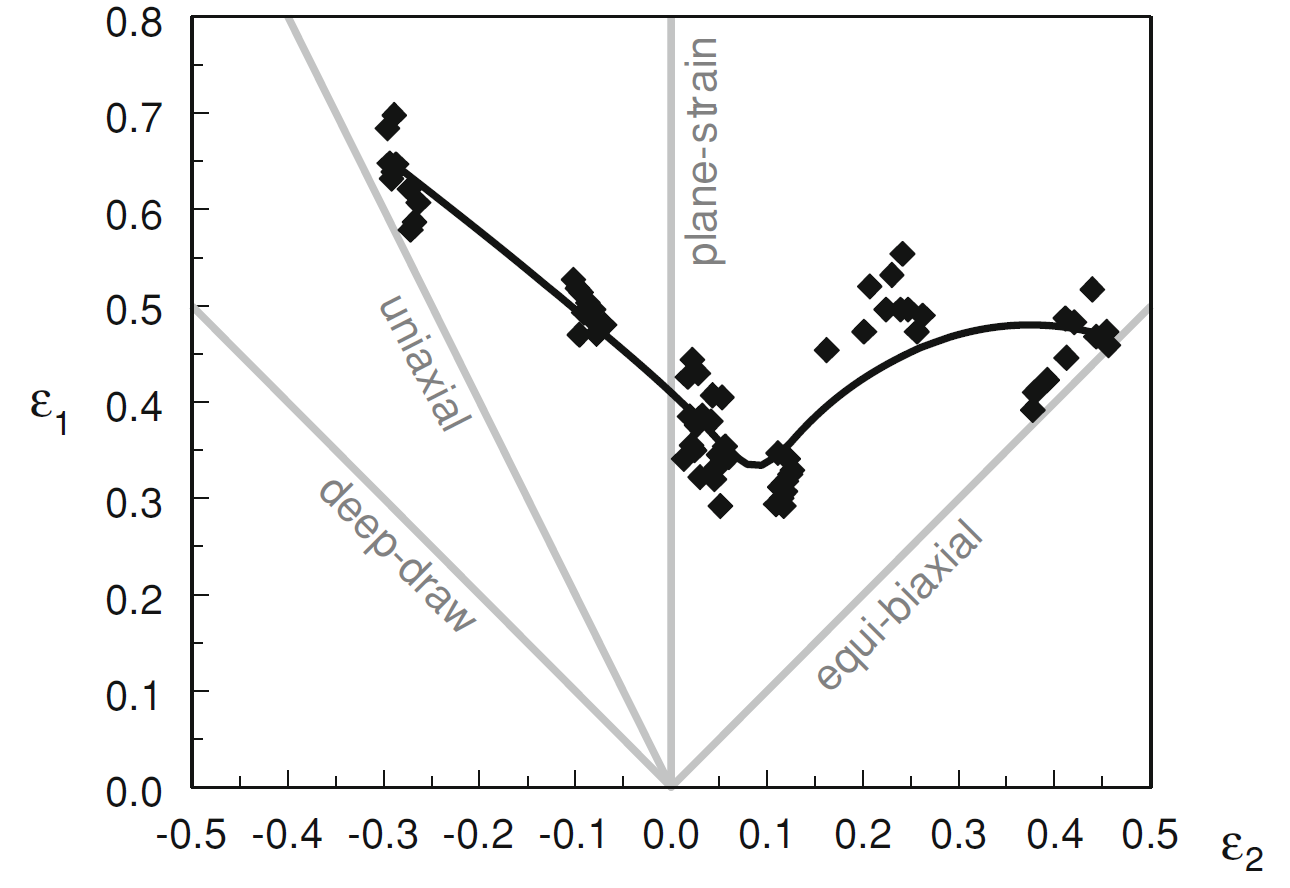
In the equation, β can be expressed either positively or negatively. Practically, the countenance ‘stress state’ is usually applied in both single combination of strains and in the circumstance where certain persistent value of β are explicitly represented in a stress state diagram by a conventional line passing through the origin as indicated using the grey lines in Figure. 1. The main explanation for the lineal representation is that most of the properties rely on the proportion ε2/ ε1. On the contrary, the properties does not necessarily depend on real values of ε1 & ε2. The connotation of the above illustration is that the mien dubbed equi-biaxial strain state is where ε1 = ε2.

A number of β values are applied to indicate circumstances that are of greater concern interest. The grey lines in Figure1 show such β values.
Table 1: β value cases.
In the circumstances that β = -1, then the expression can be viewed as in-plane shear. In fact, the diversity in the designation depends on the manner in which co-ordinate system is selected.
The development limit whether defined as a function of stress state can exist in the form of a curve as indicated in a ε1 –ε2 diagram. In fact, the resultant diagram is dubbed Forming Limit Diagram (FLD). Similarly, the resultant curve is known as Forming Limit Curve (FLC). Predictably, the FLC expresses the forming limits
Material characterisation
Aluminium (Al alloy) 6013 vs. Dual Phase Steel (DP780)
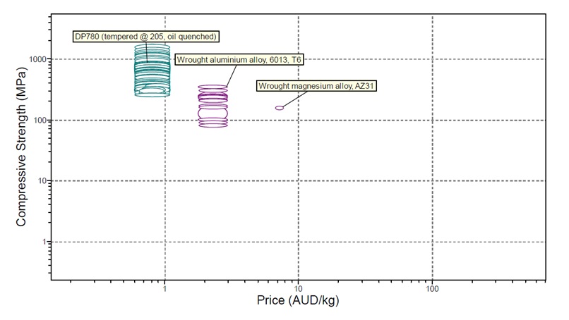
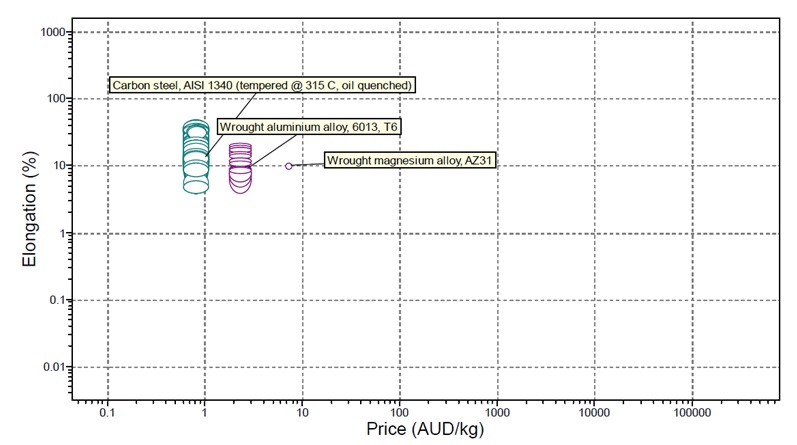
Aluminium has various applications in the manufacturing procedures. The aluminium alloy DP780 is greatly applied in the production of lightweight materials. Some of the characteristics that make DP780 to be highly used in industries include the compressive strength and elongation capability. In the modelling process, comparing aluminium with DP780 remains critical in the understanding of deformations present within the model. As can be observed in Figure 2 Dual Phase Steel 780 contains increased compressive strength of approximately 651 Mpa whereas aluminium amalgam 6013 contains a compressive power of over 351 Mpa. Another advantage with Aluminium is that it is less expensive compared with DP780. DP780 can be costly depending on the quality of the alloy. Figure 3 compares the length of DP780 and aluminium alloy 6013. While DP780 is about 0.15, the aluminium alloy 6013 is about eight. Given the qualities, DP780 is the most suitable for the project.

