Introduction
The aim of this laboratory analysis is to make a VPI transmitter Software that will be compatible with PCS operating systems. When the software installed into the computer system, it will enable the machine to monitor and investigate all operations within system parameters. VPI transmitter is simple circuit software made from integration circuit with single channel optical fiber transmission systems. Meanwhile, the report will be discussing the procedures initiated during integration processes that includes the device parameters and stating all components required to make the device. In addition, the report will be analyzing all graphs initiated as well as all the simulations processes (Berczuk and Appleton, 2005 63-76).
Procedure
Below are the procedures and the components used in the analysis to build a simulation of VPI transmitter software. From the analysis, Fig. 1 represents a Photonic link with components required as and where you can find them in the TC modules library.
- Pseudo random Bit sequence generator (TC Module> Information Coding> PRBS)
- NRZ sequence (TC Module> Information Coding> Code NRZ).
- Rise Time Filter (TC Module> Electrical Filters and DSP> Rise Time Adjust).
- Mach Zhender Modulator (TC Module> Optical Modulators> Modulator MZM).
- 193.1 THz frequency emitter LASER (TC Module> Optical Source> Laser CW).
- 100 km SMF (TC Module> Fibers> Fiber NLS)
- Optical Attenuator (TC Module> passive Components> Attenuator)
- Optical power Meter (TC Module> Instrumentation>Power meter)
- PIN Photodiode (TC Module> Receivers>Photodiode)
- Low Pass Bessel Filter (TC Module> Electrical Filters and DSP> Filter El)
- Clock recovery (TC Module> Timing and Sampling> Clock recovery ideal)
- Signal analyzer to view Eye diagram (TC Module> Analyzer> Signal analyzer)
- BER and Q factor analyzer (TC Module> Receivers> BER_OOK_Stoch)
- Fork (TC Module> Wiring tools> Fork_2)
- Grounds (TC Module> Electrical Wiring tools> Ground)
- Graph (TC Module> Analyzer> Numerical analyzer 2D)
All devices in the analysis should be set according to the global range tabulated below.
- time window = 256/2.5e9
- sample mode BW= 100e9
- sample rate default = 80e9
- bit rate default = 2.5 e9
In the rise Timer Filter, the following parameters are important to take.
- Rise time = 0.25/bit rate default
Fibre NLS
- Length= 100e3
PIN Photodiode
- Responsivity = 0.8
- Dark Curent = 0
- Thermal noise= 10e-12
- Short noise = on
Filter El:
- Filter Type = Low pass
- Transfer function = Bessel
- BW = 0.7 * bit rate default
- Filter order = 3
BER_OOK_Stoch:
- Estimation method = gauss
- Detector type = PIN
- Dark current = 0
- Short noise = No
- Thermal noise = 0
Power meter:
- Measurement mode = TOTAL
- Output units = dBm
Simulations
2.5 Gb/s
Requirement
Run the simulation by clicking the ‘Green Guy’ tool button and record the received optical power, BER and Q-factor. Note the shape of the eye opening.
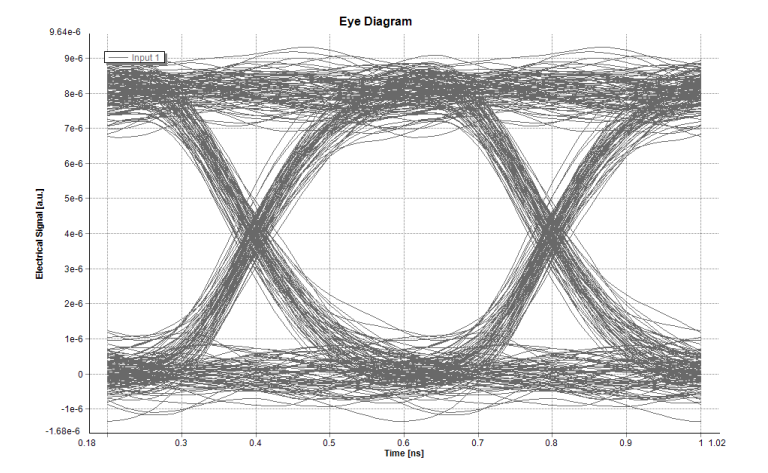
BER 4.086e-19
Q Factor 8.856
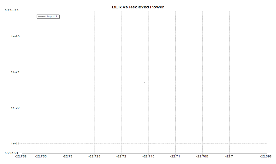
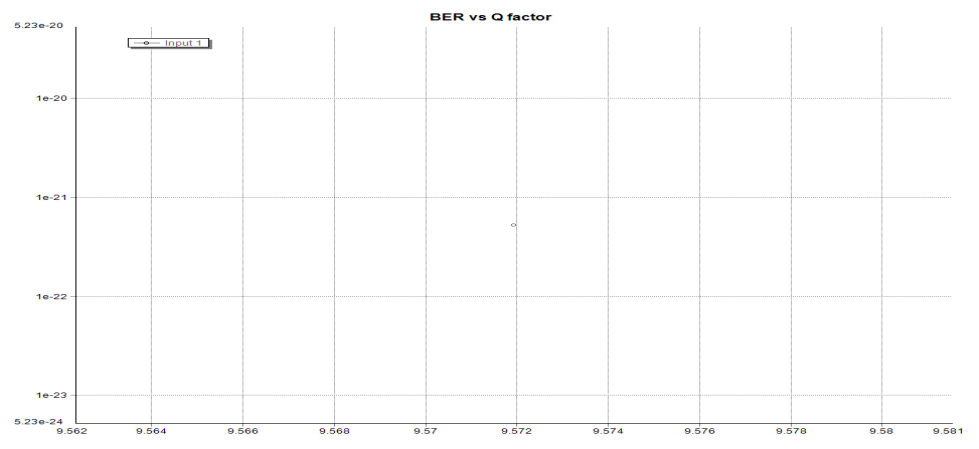
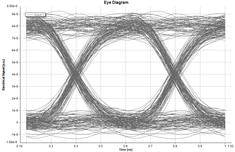
The above-mentioned figures represent the relationship between the eye patterns and the power received as well as the BER and Q factor characterized by the help of a graph on each set. The work of eye pattern is to compare different bit levels form each signal produced in the analysis. From the eye pattern graph, there is a clear observation of eye patterns during simulation process which is a characteristics of dispersion and attenuation processes having minimal BER values of 4.086E-19 and Received optical power of -22.716Bm. When the two values of BER and Received Optical powers are connected, they give a Q factor value of 8.856
Gb/s
Requirement
Run the “Attenuation Sweep” option to vary the received optical power by inserting Additional attenuation between the fiber and the photo-detector. Add 6 dB of attenuation and plot the resulting BER as a function of received power. Note that, to determine the values of eye diagram attenuation within the graph, you scroll through the simulations remembering that, each step in the graph corresponds to an increment of 1.2 dB.
From the graph analysis, there is a variation of received optical power, resulting from various changes in the attenuation sweep. During this process, an additional of 6dB attenuation signal is added to the system and the distance between the fiber and the photo-detector is 100 KM. The experiment was done by using a standard universal fiber that has an attenuation factor of 0.2 dB/Km. Moreover; an addition of 6dB of attenuation factor to optical fiber system is synonymous to extra 30KM. Finally, the achievement of five (5) eye pattern and BER graphs is realized when there is an increment size of 1.2dB to the optical fiber system.
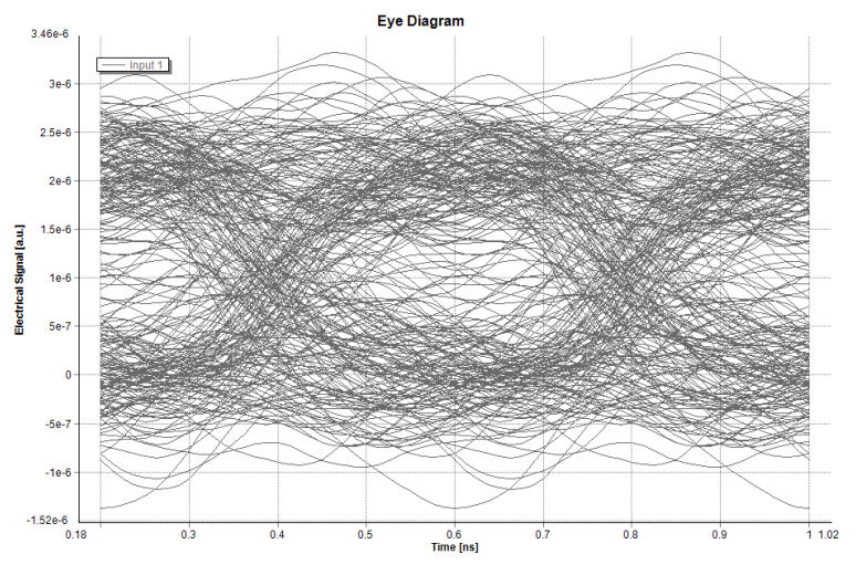
BER 0.01376
Q Factor 2.2
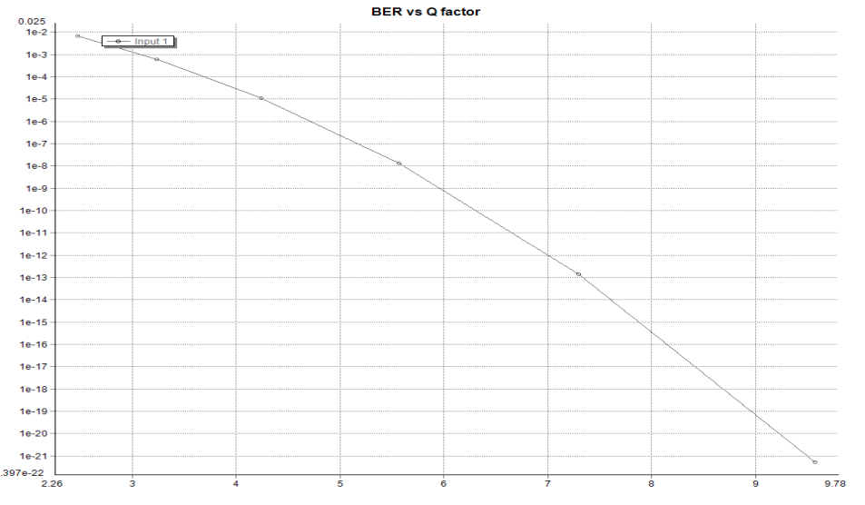
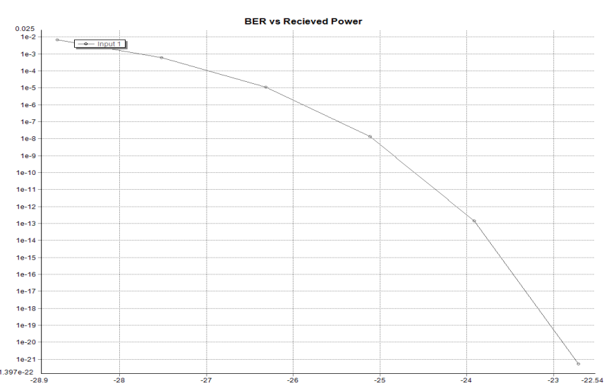
From the above figure, the resultant eye pattern is affected when there is an increase in attenuation factor. Meanwhile, fiber attenuation on the eye pattern and BER is affected by some minimal changes and this eye pattern dispersion cannot be noticed due to the presence of bit rate. From the graph 2.3, the higher the received optical power values, the lower the BER value. Finally, to achieve higher Q value, you need to have a lower BER values as deduced from the graph 2.2.
Determine the maximum fiber length over which a 2.5 Gb/s system with the same Parameters can achieve a BER of 10-9.
Solution
Maximum fiber length can be calculated from the graph parameters when the average transmitting laser power is given, which is equivalent to 1mW. However, when the BER is 10.9, the received optical power is -25.3dBm. Fiber attenuation is 0.2 dB/Km as deduced from the graph of BER against Received optical power.
Reduce the length of the fiber to 50 km and re-run the simulation. Observe the shape of the eye diagram. Explain why the amount of noise on the ‘0’ and ‘1’ levels is different.
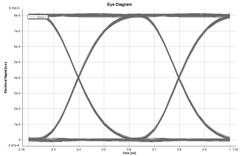
BER : 0.
Q Factor: 81.469
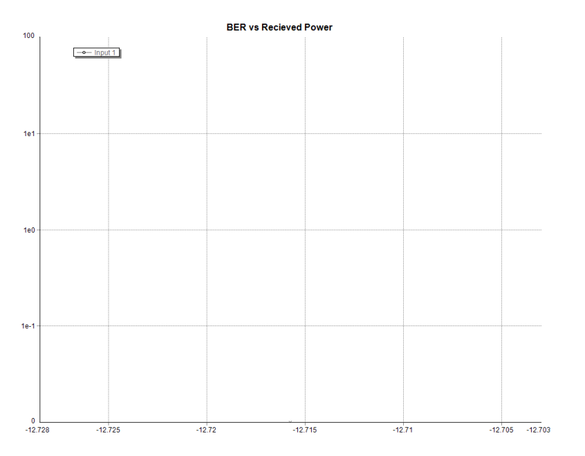
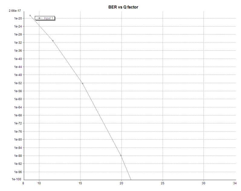
There is a big difference between the Q factor, BER against Q factor and BER against Received power values when we compare their figures within a length of 100KM. Meanwhile. When the length of simulation is 50KM, the effect of eye pattern attenuation and the graph deduced is lower, hence; when we have wide-open eye pattern, then the level of attenuation is lower. When you compare BER against Received power graph and BER against Q-factor graph within a range of 50-100KM, BER value is 0 when the fiber length is at 50KM. This is an equivalent of -13dBm of received optical power, which is higher than the optical power recorded within a distance of 100KM length. Meanwhile, when the BER is low, the value of Q-factor is high and has a higher value of 81.469.
10 Gb/s
Requirement
Change the bit rate to 10 Gb/s and re-set the average laser power to 1mW. Keep the fiber length at 50 km. as you run the simulation and record the received optical power, BER, and Q-factor. You should note the shape of the eye’ diagram and know what has caused the shape to occur.
The comparison of this eye pattern results has shown that, signal transmission is hardly affected by the position of fiber attenuation signal hence noise level on the eye pattern has a lower value. There is an increase of bit rate before the simulation process, which leads to pattern distortion as compared from the previous results. Hence, dispersion affects the normal working of the transmission signal.
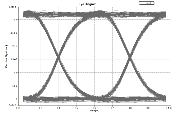
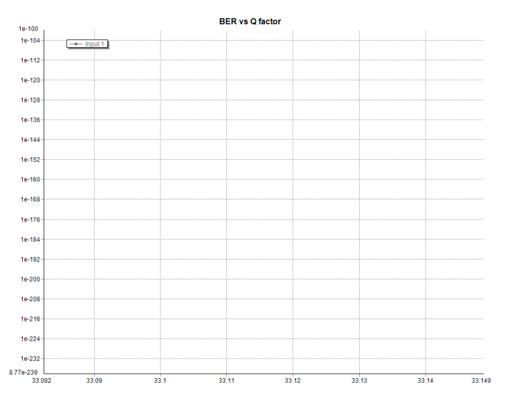
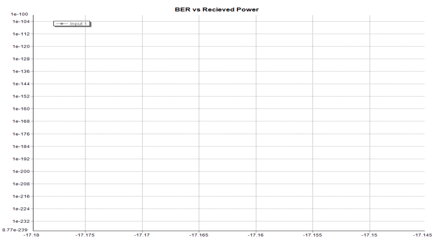
BER: 8.77368e-241
Q Factor: 33.11
BER 2.6638e-19
Q Factor 8.904


BER 0
Q factor: 227.236


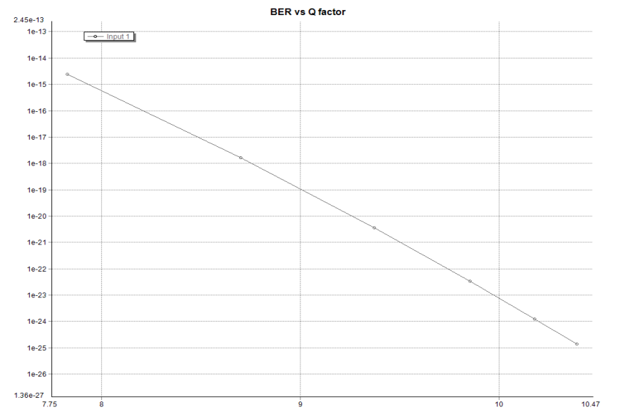
Run the “Attenuation Sweep” and plot the resulting BER as a function of received power. This analysis is examining the sweep attenuation signal that is affected by the eye patterns dispersion, which corresponds to the initial simulations. However, when the value of BER decreases the values of received power increases. In addition, an increase of eye pattern leads to an increase in simulation as deduced from this result analysis. Similarly, an increase in Q- factor leads to a decrease in the values of BER.

BER 1.36e-25
Q factor: 10.39


Requirement
Calculation of the maximum fiber length for a BER of 10-9 at 10 Gb/s.
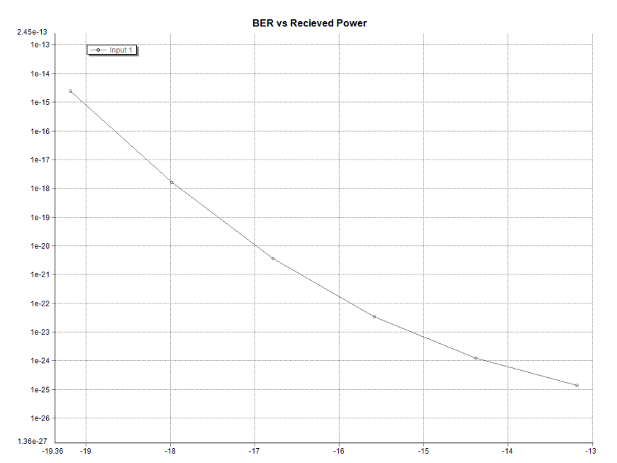
Here, the calculation of maximum fiber length is calculated by keeping all the parameters constant without adjusting their figures. When a graph of BER against Received Optical Power is plotted, the values of average transmitting laser power is 1mW=0dBm and the received optical power is -19dBm when BER is 10-15, leading to an attenuation fiber value of 0.2dBm/Km. Moreover, Link Loss is given by the difference between the Transmitted power and Received power. This Link loss can be used to calculate Maximum Fibre Length, which is a ratio of Link loss against Attenuation Factor i.e. Maximum Fibre Length=Link loss/Attenuation Factor.
19 dBm/ 0.2 dB/km = 95 km

BER 2.45e-15
Q factor: 7.8289
Requirement
Observe the effect of fiber dispersion by changing the laser line width to 200 MHz by observing the effect on the shape of the eye diagram. Plot the BER versus received power. For a BER of 10-9, what is the ‘dispersion penalty’ when the fiber length is 50 km and the laser line width is 200. The analysis from this stage has shown that the line width changes when dispersion effect is observed on eye pattern graph plotted against BER graph. For the above results to happen, the two line width values must be 10MHz and 100MHz respectively.
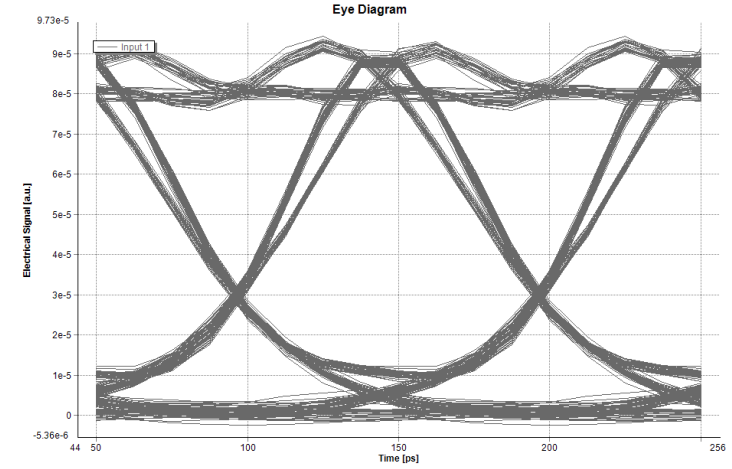
BER 1.3833e-25
Q factor: 10.388
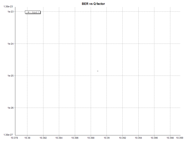
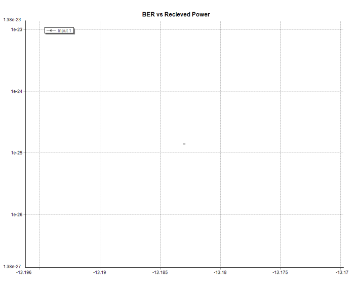
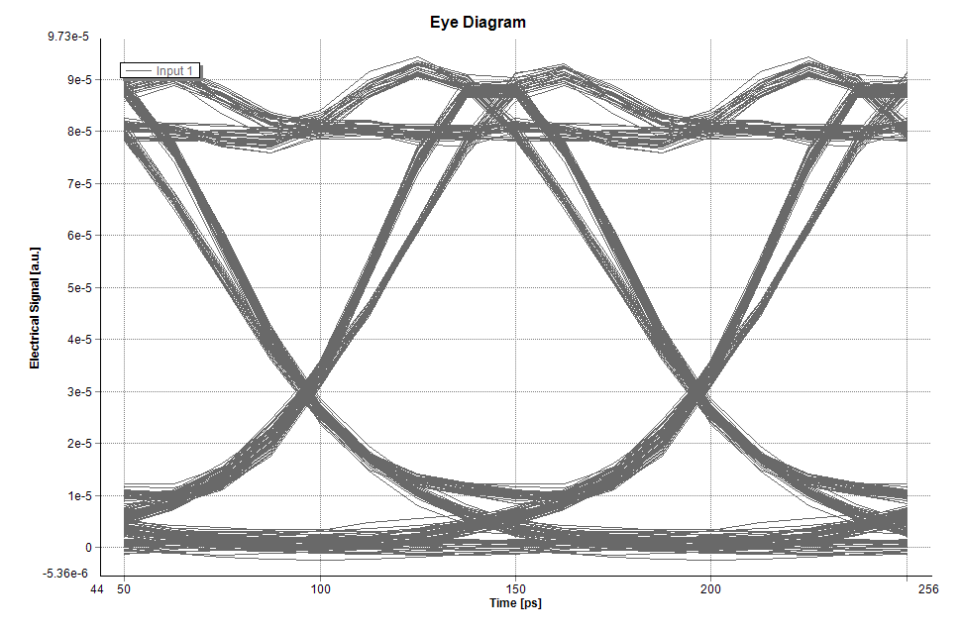
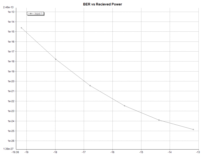
From the above figures, a comparison is made on eye patterns within a range of 10MHz and 100MHz, hence; when the eye patterns is at 100MHz, the dispersion level is higher than the first one. However, the level of signal dispersion is affected by the line width-one of the factor that affects the dispersion level. Meanwhile, an increase of BER values also affects the level of signal dispersion.
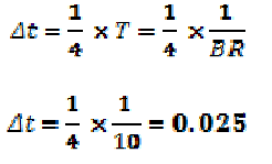
Dispersion Penalty =
Requirement
Determine and plot the sensitivity (minimum received optical power for a BER of 10-
Of this 10Gb/s system as a function of fiber length. Use fiber lengths of 20-60km. You may need to change the laser output power to get sensible results.
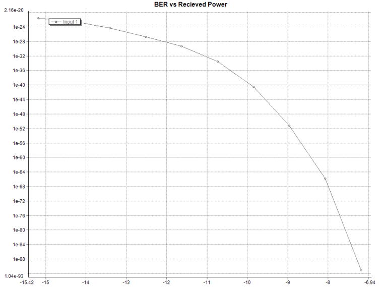
Sensitivity is the minimum optical power required to attain a definite bit. Error Rate sensitivity is part of optical power sensitivity pattern measured in dBm. It is a fundamental unit that measuring the sensitivity of most devices (Sackinger 2001, 21 – 32).
Conclusion
Overall, the aim of the experiment analysis is to make VPI transmitter software that when installed into PCS machines, it works efficiently by monitoring the flow of optical fiber system and its simulations. This can only achieved when we consider the level of simulation performed, monitoring eye pattern, BIT error Rate (BER) and the Q-Factor as well as the received Optical power. All the analysis has been achieved through comparison of several behaviors and changes within BER and Q-Factor as well as Received Optical Power. The effect of attenuation is regarded as a bigger problem affecting the normal dispersion of signal, hence; the graphs have been used to investigate and tabulate faults within optical fiber systems components.
Reference List
Berczuk, S. and Appleton, B. (2005). Software Configuration Management Patterns: Effective Teamwork, Practical Integration (Software Patterns Series)(Paperback).United Kingdom: Capstone Publishers, Inc.
Sackinger, E. (2001). Broadband Circuits for Optical Fiber Communication (Hardcover). New York: Springer Publisher.