Abstract
Advancements in the creation of vehicle components with the inclusion of modern technology has played a critical role towards the development of advanced hardware components that many manufactures have used to fashion internal combustion engines adhering to drivability, improved fuel economy and stricter emission regulations.
A turbocharger is an invention of Alfred Buchi (1879-1959), a Swizz engineer who used an exhaust gas driven compressor to increase the power of a diesel engine. A turbo charger used by an automotive is made up of a turbine, a compressor and a couple of common shafts.
A turbine is a pivotal part which initiates the process of energy accumulation. It captures kinetic energy produced by exhaust gases emitted during combustion. Turbo charged engines have various compartments which direct the flow of gas.
This flow is directly proportional to the air and amount of fuel that are sent to the cylinders. Since they are equal, the difference in size of the engine is critical since it determines the amount of power an engine produces. This implies that there is larger amount of flow in air which consequently increases the power of the engine.
Introduction
Advancements in the creation of vehicle components with the inclusion of modern technology has played a critical role towards the development of advanced hardware components that many manufactures have used to fashion internal combustion engines that can adhere drivability, enhance improved fuel economy and stricter emission regulations.
Awareness on sustainability from economic, social and environmental perspectives is indeed growing due to observable changes in society. There are numerous legal and social systems that have been developed by governments and even the business community to ensure that this critical aspect is addressed.
When a turbo engine has been integrated into one engine configuration, significant interactions and nonlinearities occur within it. The latter eventually results into the need for more advanced control methods [11]. Therefore, emission regulation has prompted the need for increased power of the engines, external gas recirculation system as well as drivability.
Purpose
An understanding of the main purpose of this paper is very important as it highlights the findings from various publications on turbo charged engines and their effectiveness in enhancing condition of an operating engine to meet engine safety, low emissions, fuel economy and fast torque response.
The findings from the publications and other related articles on turbo charged engines will be critical in making particularistic conclusions on its efficacy in terms of increase in the power of engines, low emissions, fuel economy and drivability.
Scope
The scope of this report is limited to turbo charged engines, components and functions, and how a turbo charged engine can be effective when compared to non-turbocharged engines. In this respect, the paper gathers various findings from different articles as well as experimental literatures that have explained the various models of turbo engines.
Assumptions
There are quite a number of key assumptions that have been made to ensure that the objective of the paper is conformed to. One such assumption is that a turbo charged engine is more effective compared to a conventional supercharger.
This is due to the fact that the latter is driven mechanically while the former uses engine exhaust gas turbine. Bedsides, compared to a naturally aspirated engine, a turbocharged engine is more powerful. This is attributed to the increased air intake and more combustion of fuel due to turbine forces.
Turbo charged engines. A brief history of turbo charged engines
A turbocharger is an invention of Alfred Buchi (1879-1959), a Swizz engineer who used an exhaust gas driven compressor to increase the power of a diesel engine. It is worth to mention that this practice of forced induction had earlier been tried by Gottlieb Daimler among other engineers during the 19th century.
Before turbochargers, the use of superchargers for forced induction was common. In the 1920’s, turbochargers were used in the production of engines of aircrafts. It later spread to the use of turbocharged diesel engines on ship and locomotives.
The working principle of the Turbo charged engine
A turbo charger used by an automotive is made up of a turbine, a compressor and a couple of common shafts. The exhaust gas of an automotive engine has a critical role of propelling the turbine. The force drives the compressor and directs the compacted ambient air into an intake manifold.
The increased supply of air is very critical in the provision of a larger output supply into engine cylinders [15]. This causes the burning out of large fuel quantities. Unlike in non-turbocharged engines, turbo-charged engines allow for a larger torque output from the large quantity of burnt fuel.
It is imperative to highlight that turbo charged engines have improved operation efficiency at lean air-to-fuel ratio. This leads to improved fuel economy.
Turbo charged engines have regulated engine emissions consisting of carbon monoxide (CO), Hydrocarbons (HC), Oxides of Nitrogen (NOx) and particulates (PM). The reduced particulate emissions due to turbo charging emanate from increased temperature, air charge densities, and air to air fuel ratios [7].
It is imperative to note that the aforementioned factor increases oxygen availability. Temperature gives rise to the formation of NOx. The latter can be partially offset when air charge temperature is reduced. This is a function of an intercooler on turbo-charging. The intercooler also reduces particulate emissions by increasing the density of air charge.
At regulated levels, NOx emissions cannot be sufficiently regulated. As such, an exhaust gas recirculation system (EGR) is required to divert back the emitted exhaust gas into the intake manifold. The portion of the gas is then used to dilute the air that the compressor supplies.
Besides, the diluted air within the cylinders increases the charge specific heat capacity and also plays the role of inert gases. The gas impacts negatively on the formation of NOx emissions, lowers the temperature of peak flames and reduces the rate of burning.
Typically, the circulation of exhaust gas is a process that is accomplished in the valve of an exhaust gas recirculation tube that links the intake manifold with the exhaust manifold.
Besides, certain configurations of some diesel engines have been designed to include an intake manifold linked to a compressor with EGR throttle. The latter enhances EGR rates by creating the needed pressure drop on the valves.
Components of Turbo-charged engines
In order to achieve a properly functioning system, a turbocharger is subject to several applications. The interplay of various major components of an engine is critically a function of a smooth synchrony of all the components [1]. Each part which makes up a turbo charged engine is significant.
It is imperative to note that all components have to work together in order to achieve all the necessary processes. Turbochargers are made up of three major components. These include;
- A turbine- this is an inflow radial turbine
- A compressor- it is majorly a centrifuging compressor
- A central hub- this makes the main rotating set of the engine
Turbine
A turbine is a pivotal part which initiates the process of energy accumulation. It captures kinetic energy produced by exhaust gases emitted during combustion. It has sections which direct the flow of gas. Besides, in its normal performance, the turbine spins at a velocity of about 250,000 rotations per unit time [5].
In its determinant functions, shape and size characterize the overall output. Assemblies of turbo chargers combine different specifications of the engine according to numerous set ups of turbine compartments. It is therefore possible to determine the efficiency responsiveness and performance of a turbo charger. This is achieved through the mentioned choices of turbine attributes.
Turbine wheels are fitted to regulate the amount of gas flowing through the system. Their sizes are chosen in relation to expected outcomes. In general, large flow capacities are achieved through the use of large turbine wheels. This direct relationship is essential in making developments in turbo charger engines [6].
The performance of these engines is related to their sizes. Large ones have a high heat intake and spin the turbine with a turbo lag hence they achieve low rates of rotation [6].
Smaller turbochargers tend to attain higher acceleration. This does not mean that size is tagged to advantages. Both small and large sizes have demerits. Indeed, innovations of schemes which counter the drawbacks of size have led to designing of combined models;
- Twin turbo- This is made up of a pair of turbo chargers which have been set to operate parallel to each other or sequentially. When placed in parallel, the two are connected in manner which enables them to share the engine’s exhaust chamber in 50-50 basis. In a sequential arrangement, the two run at different speeds. One runs at the resultant speed of the engine while the other runs at a lower regulated speed. Small turbo twins realize lower lags compared to large ones. This configuration is highly adopted especially in boxer engine and V-shapes [8].
- Twin-scroll- These have a double inlet of gas. Smaller ones have more rampant responses compared to bigger ones. To attain a peak performance, twin-scrolls are configured at different time configurations. This is done at the camshaft and in every exhaust valve. Timing is normally customized to enable the system to recover quickly after generated energy is lost.
- Variable-nozzle turbo – These use vanes to adjust air flow. They have a combination of sizes which have been made to give the engine optimal power output. Vanes are inserted at the front of the turbine to form slight overlaps with one another.
The angle of overlap is joined to actuators which act as control devices. The variability emerging from this arrangement creates back pressure when the engine is in function. Notably, this is important in making the engine become more fuel efficient [10]. Growth of turbo lag is also minimized significantly.
Compressor
The engine has a centrifugal compressor. The compressor is made up of four parts. These include a collector, diffuser, a rotor and an inlet. This component is the chamber for gas work. As gases pass through the compressor, consequential energy is tapped axially from left to right. The impeller is placed strategically in the downstream of a discharge cone. The four components are described below.
- The collector– it takes many different shapes. Its form is also chosen in relation to centrifugal compression. The collector of a turbo charger has empty chambers for collection. It has a direct connection to the diffuser such that it gathers the total flow of the diffuser. A collector contains numerous valves which are instrumented to control it. The specially adapted valves are referred to as blow-off valves.
- Inlet– It takes the simple structure of a pipe. It feeds the compressor. It is made up of stationary air vanes and valves. The foils are fitted to manage flow of fluid. They swirl the flow such that both temperature and pressure are kept in control. It should be noted that the inlet takes a central role in controlling a compressor. This is the reason it has such specialized features [13].
- Rotor– This makes the key part of a turbo charger’s centrifugal compressor. It is also referred to as the impeller and has a rotating set of parts. It has blades which are arranged uniformly. These blades rotate and determine the working gas energy.It resembles axial compressors in that its radius increases causing an acceleration of the gases’ energy and velocity levels. Innovations have been put in place in modern day compressors. A good example is the production of high efficiency compressors. The high speed compressor rotors which are able to exit gas at a speed close that of the sound which they produce [13].
- Diffuser– It is placed downstream to the rotor. It lies at the flow path so that it can have the ability to change kinetic energy of working gas into force which applies pressure. This is achieved through diffusing the gas at a velocity which is lower than its original one. A diffuser has different forms and combination of alternating vanes. The combinations are sometimes made hybrid through the inclusion of pipes channels and wedges.
Rotating assembly
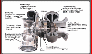
The rotating assembly has a shaft which connects the turbine and the impeller of the compressor [12]. It contains a system of bearings which support the shaft. This allows the shaft to rotate with maximum speed without much resistance.
The rotating assembly uses special bearing balls which depend on pressurized oil. It has a coolant which circles it. This can be water, oil or gas made depending on the heat expected from the turbine.
The ball bearings used here are very important. They have to be thrust to maximize their durability. This is because they play a heavy task. The coolant instrumentation is venerated in every segment because produced heat is transmitted around the whole system.
The operations of a turbo engine
As noted earlier, the power of a turbo engine is directly proportional to the air and amount of fuel that are conveyed to the cylinders. Since they are equal, a difference in the size of engine is critical in the amount of power an engine produces [6].
This means that more air flow in larger thereby making their power greater. Smaller engines can be made to work similar to larger ones in terms of power. This can be achieved by supplying more air into a cylinder. In order to dramatically increase the power and performance of an engine, many engines are installed with a Garret turbocharger [2].
A turbocharger is made up of several components that include (See figure below):
- A compressor inlet
- A compressor discharge
- A charge air cooler
- Intake valve
- Exhaust valve
- Turbine inlet
- Turbine discharge
Figure 1: A turbo system
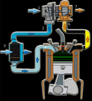
As the diagram illustrates, ambient air passes through an air filter and is directed to a compressor which increases its density after the air volume has been compressed. The effect of the cooling the engine results into strong resistance against detonation and increase in density (mass/volume of air).
The fourth component in the diagram forms the intake manifold, a section where air passes before entering the cylinder. The mass and rate of flow of air in the cylinder in normally enhanced. This is attributed to the elevated density of compressed and cooled air as well as the fixed volume of air in the cylinder.
As indicated earlier, when the flowing rate of mass of air is high, fuel flow rate also increases at the same fuel to air ratio. The effect of the flow of air and subsequent combustion of fuel is more engine power for every displacement or engine size.
Additionally, the combustion of fuel which causes its complete burning allows the product to be exhausted via the exhaust manifold. The turbine receives the high temperature created from the combustion and creates backpressure.
This is important in the sense that it shows that the engine exhaust pressure is higher than the pressure of the atmosphere. A drop in temperature and pressure causes turbine expansion which in turn harnesses the energy of the exhaust gas. The energy is very important in the provision of enough supply of power to drive the engine compressor.
Turbochargers are different in size and are specific to particular engines. This quality allows it to provide a response of rapid flow of air at low engine speed when there is a demand for acceleration. The air that flows into an engine cylinder causes an increase in the rate of fuel flow and engine torque.
This effect is normally reached when the flow area of a turbine is small [3]. The size enhances a manifold pressure increase from the exhauster, a factor that increases the generation of power. The latter being a function of turbine results into an increase in fuel rate.
Controlling damages on turbo charged engines
It is worth mentioning at this point that a turbo charged engine may be damaged under extreme cases of air flow. At high loads and engine speeds, and excessive difference between intake manifold pressures and the exhaust is created [14].
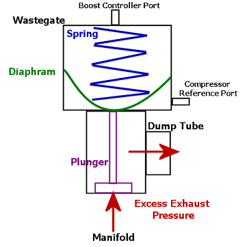
This in turn increases the amount of intake manifold pressure leading to engine damage. In order to avoid such damages and other related negative consequences, a turbo charged engine must be deigned to contain a wastegate [9]. The latter is normally opened when an engine is at high speed. Its opening is vital in the sense that it allows a bypass of exhaust gas in the turbine.
A wastegate is important because it aids in controlling an engine’s boost pressure. internal and external use by some diesel and gasoline applications provide a bypass to engine exhaust flow. This is a process that occurs at the turbine wheel and matches the power driving the turbine to the given boost level.
According to the boost control theory, wastegates reduce the exhaust flow, a ,similar function conducted by the BOV which makes use of the spring force and boost pressure to regulate the exhaust flow bypassing the turbine.
Figure 2: A diagram showing a wastegate
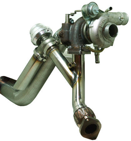
Figure 3: A diagram showing a wastegate
Internal wastegate
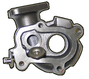
An internal wastegate is an important component built and located on a turbo. It has an actuator with a diaphragm which controls the gate leading to the turbine wheel. The location of an internal wastegate as the name suggests is within the turbine housing [4].
The waste gate is made up of a pneumatic actuator, a rope end, a crank arm and a valve. Some of the main advantages of the wastegate are the fact that it does not require an intake manifold and that it is very compact. Even so, many analysts are of the view that just as it has its pros, its cons can cause damages to an engine.
One such limitation is the notion that it is made to fit within the turbine housing, a consideration that denies it the ability to allow maximum flow of exhaust CFM. Besides, the location inside the turbine causes turbulence and limits turbo performance.
Figure 4: A diagram showing an interal wastegate
External wastegate
An external wastegate is a component made on the header or exhaust manifold. This unlike the internal manifold is not made inside the housing of a turbine. As such, its performance is enhanced. The external wastegate allows the re-introduction of the by-passed flow into the exhaust and turbine streams.
Another approach against damages is the use of a variable geometric charger (VGT). This component grants more flexibility, limits the use of wastegate, shapes engine torque response, reduces emissions and improves fuel economy. The variable geometry turbocharger has a turbine stator which has pivoted guide vanes [1].
Figure 5: A figure showing the components of a turbocharger
Basic operating principle
An engine with a turbo charger has improved engine volumetric efficiency which comes from the density of the air taken into it. The ambient air is drawn into the compressor with each intake stroke drawing a mass of air. Kinetic energy needed to spin centrifugal compressor comes from the engines exhaust gases.
In order to increase power, a turbo charged engine recovers waste energy and re-takes back into the engine. It is worth noting that during combustion of fuel; a lot of energy is emitted. This increases the temperature leading to Carnot efficiency.
Conclusions
To sum up, a turbo charged engine exhibits more power and increased fuel efficiency of an engine. As noted in the paper, advancements in the creation of vehicle with the inclusion of modern technology has played a critical role in the development of advanced hardware components that many manufactures have used to fashion internal combustion engines adhering to drivability, improved fuel economy and stricter emission regulations. Turbochargers are aided by components such as ball bearings, turbine blades and wastegates.
References List
- Baratta, M., Spessa, E., and Mairone, P., “Numerical investigation of turbolag reduction in HD CNG engines by means of exhaust valve variable actuation and spark timing control,” International Journal of Automotive Technology, 11(3): 289-306, 2010, doi: 10.1007/s12239-010-0037-x
- Capus, J.M., “SAE 2001: PM industry still on the move despite slowdown”, Powder Metallurgy, 44(2): 113-113, 2001.
- Capus, J.M., “SAE World Congress 2002: better times ahead?” Powder Metallurgy, 45(2): 110-111, 2002.
- Eroglu, M. and Onalp, S., “Tungsten inert gas surface modification of SAE 4140 steel”, Materials Science and Technology, 18(12): 1544-1550, 2002.
- Galindo, J., Climent, H., Guardiola, C., and Doménech., “Strategies for improving the mode transition in a sequential parallel turbocharged automotive diesel engine,” International Journal of Automotive Technology, 10(2): 141-149, 2009, doi: 10.1007/s12239-009-0017-1.
- Hunziker, R., H-P Dickmann and Emmrich., “Numerical and experimental investigation of a centrifugal compressor with an inducer casing bleed system,” Proceedings of the Institution of Mechanical Engineers, 215(6): 783-783, 2001.
- Ilardo, R. and Williams, C.B., “Design and manufacture of a Formula SAE intake system using fused deposition modeling and fiber-reinforced composite materials”, Rapid Prototyping Journal, 16(3): 174-179, 2010.
- Kim, H.G. and Jeon, S.I., “Effect on friction of engine oil seal with engine oil viscosity”, International Journal of Automotive Technology, 9(5): 601-606 2008, doi: 10.1007/s12239-008-0071-0.
- Kim, J. N., Kim, H. Y., Yoon, S. S., and Sa, S. D., “Effect of intake valve swirl on fuel-gas mixing and subsequent combustion in a CAI engine,” International Journal of Automotive Technology, 9(6): 649-657, 2008, doi: 10.1007/s12239-008-0077-7.
- Kirk, R. G., Alsaeed, A. A., and Gunter, E. J., “Stability analysis of a high-speed automotive turbocharger,” Tribology Transactions, 50(3): 427-434, 2007.
- Rakopoulos, C. D. and Giakoumis, E. G. Review of thermodynamic diesel engine simulations under transient operating conditions. SAE paper 2006-01-0884. Also Trans. SAE, J. Engines, 2006, 115, 467-504.
- Rakopoulos, C. D., Giakoumis, E. G., Hountalas, D. T., and Rakopoulos, D. C. The effect of various dynamic, thermodynamic and design parameters on the performance of a turbocharged diesel engine operating under transient load conditions. SAE paper 2004-01-0926, 2004.
- Serrano, J. R., Arnau, F. J., Dolz, V., Tiseira, A., Lejeune, M., and Auffret, N., “Analysis of the capabilities of a two-stage turbocharging system to fulfil the US2007 anti-pollution directive for heavy duty diesel engines,” International Journal of Automotive Technology, 9(3): 277-288, 2008, doi: 10.1007/s12239-008-0034-5.
- Taraza, D., Henein, N., and Bryzik, W. Friction losses in multi-cylinder diesel engines. SAE paper 2000-01-0921, 2000.
- Turner, J. W. G., Pearson, R. J., and Bassett, M. D. ‘Performance and fuel economy enhancement of pressure charged SI engines through turboexpansion – an initial study’. SAE paper 2003-01-0401, 2003.