Summary
Friction opposes sliding and depends on the roughness of surfaces in contact. This proportion is called the ‘Coefficient of Friction’ and is denoted by the symbol μ (pronounced ‘mew’). Friction which opposes movement from rest is called ‘Static Friction’. As soon as sliding takes place it is found that less force is required and is called ‘Kinetic Friction’. Friction is mainly depended on the nature of the surfaces and not the area of contact between the surfaces.
The experiment was carried out to determine how kinetic and static friction varies and how the coefficient of friction varies with increased load or pressure on a surface and the type of material used. Wooden, metallic and rubber surfaces were used. It was found that the area of surface contacts and the amount of normal force applied to the surfaces does not influence the friction; rather, the nature of surfaces used for friction was the main contributor to the value of coefficient of friction.
Experimental Objective
The objectives of this experiment is to verify the laws of friction, the different types of friction (static and kinetic friction) and how the type and nature of surface on which friction takes place determines the coefficient of friction. In particular, three surfaces are investigated. These are metal on metal, wood on wood and metal on rubber.
Theoretical Background
Smooth surfaces are normally characterized by the nature in which they lie perpendicular to their tangent plane when they come in contact. Nevertheless, no surface however smooth it is lacks friction (CodeCogs Engineering, 2009).
Friction can be defined as the resistance to sliding when two or more surfaces are in contact with each other. The frictional force is the force that inhibits the relative motion between the surfaces. Uneven particles between the surfaces are the main cause of friction. Therefore, in order for sliding to occur, this force has to be overcome.
Different laws of friction exist. These are:
- The magnitude of the friction between surfaces does not depend on the contact area.
- The coefficient of friction (μ) depended on the composition or nature of the surfaces (the materials the surfaces are made of) tends to limit the friction when a normal force is applied.
- The direction of friction is always opposite to the direction of motion or the direction in which sliding occurs and does not depend on the velocity of the bodies.
- The frictional force is normally adequate in preventing friction for bodies in equilibrium and thus can easily be calculated through the application of conditions of equilibrium (CodeCogs Engineering, 2009).
Static friction is defined as the friction that inhibits motion of surfaces from rest while kinetic friction occurs for surfaces already in motion. The coefficient of static friction is normally greater than the coefficient of kinetic friction.
Friction has both its positive and negative aspects. In particular, friction is very essential in the braking system of vehicles. However, it causes wear and tear in machines making them consume more power.
Experimental Procedures
Equipment used: Sliding friction equipment, friction surface plate and block with cord, knurled nuts, weight hook, 10N spring balance, set of weights and plumb bob and line.
Equipment setup: The mounting panel was put in the vertical position and the plane assembly mounted by placing the stud through hole H4, the stud on column through C8 and secured with nuts. The plumb line was hanged over the protractor center screw and the plane ensured to be horizontal. The center support was adjusted. The friction block was weighed with the spring balance and its weight recorded then placed on the left hand end of the plane with wood surface downwards and assembled cord over pulley. The 0.1N weight hook was attached at the end of the cord.
Procedures
Test 1: Weights (about 0.8N) were placed on the hook and the block given a starting push as each weight was applied until the weight was sufficient to pull the block along the plane in a uniform speed. The weight of the friction block (R) and the force required to overcome kinetic friction (Fk) were recorded.
Test 2: The procedure for test 1 was repeated but the block was not given a push. Instead, weights of about (0.1N) were placed on the hooks until the block began to move due to the cord’s pull only. The force on the friction surfaces (R) and the force required to overcome static friction (Fs) were recorded.
Test 3: The block was turned on its narrow side and the same procedure as test 1 done. The force on friction surfaces and the force to overcome static friction Fs were recorded. The test was repeated with the other narrow side of the block and the force required to overcome kinetic friction recorded.
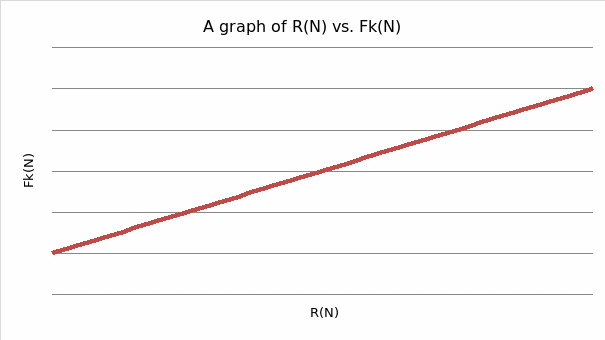
Test 4 (wood on wood): The friction block was replaced in its original position as for test 1. Loads of 0.5, 1, 2, 3 and 4N were added in turn to the friction block. The equivalent forces to overcome kinetic friction were determined. The results were then tabulated and a graph of R verses Fk plotted.
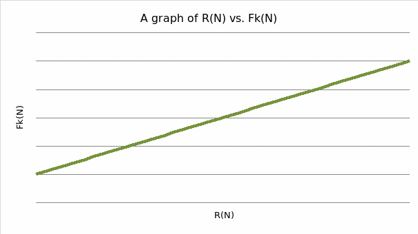
Test 5 (metal on metal): The friction plate was placed on the plane between the stops with its metal side upwards. The loading peg on the friction block was reversed and placed on the plate with its metal side downwards (to obtain the metal on metal contact). Loads were added as in test 4 and the results recorded and tabulated and a graph of R verses Fk plotted.
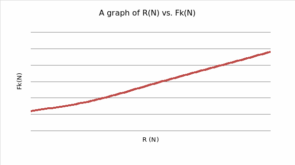
Test 6 (metal on rubber): The friction plate was turned to ensure the rubber side was upwards to give metal to rubber contacts. The block was made to move at constant speed along the length of the plane in about 10secs. Loads were added as in test 4 and the results for Fk tabulated and a graph of R verses Fk plotted.
Experimental Data
- Test 1: R= 1N and Fk = 0.18N
- Test 2: R = 1N and Fs = 0.20N
- Test 3: R=1N, Fs =0.20 and Fk = 0.18N
- Test 4: Tabulated results with R = added load + weight of block
- Test 5: Tabulated results with R = added load +1N
- Test 6: Tabulated results
Data Analysis

From the graph, the gradient is obtained as 0.2 which represents the coefficient of friction when the surfaces are wood on wood.
Fk =μR
Y= mx; m=μ =Δy/Δx =1-0.4/(5-2) = 0.2
From the results, the coefficient of friction does not vary with load (it remains constant).

Similarly, the gradient of the graph yields 0.2 which represents the coefficient of friction on metal surfaces. The coefficient does not vary with added load but remains constant.
Fk =μR
Y= mx; m=μ =Δy/Δx =1-0.4/(5-2) = 0.2

From the graph, the gradient of the line is found to be 0.514.
Discussion
In test 1 and 2, the static and kinetic frictions were obtained. In test 1, the kinetic friction was found to be 0.18N while in test 2, the static friction was found to be 0.20N. From these results, it is seen that the static friction is slightly greater than the kinetic friction. In test 3, the kinetic friction obtained was 0.18N which did not vary from that obtained in test 1. This implies that the area of contact does not affect the friction. Tests 4,5 and 6 demonstrate the effect of the surfaces nature on the coefficient of friction. When the pressure between surfaces is great, the coefficient of friction is also large (as seen in test 6). Between surfaces of similar materials, the coefficient of friction is not very large (test 4 and 5).
The actual coefficient of friction between wood surfaces is 0.2 which tallies with the experimental results. Similarly, that between metals surfaces is 0.2 which tallied with the experimental results. For, metal/rubber surfaces, the actual coefficient is >1 while that obtained in the experiment was 0.51. There is a variation due to the weariness of the surfaces.
Conclusions
The experiment was able to demonstrate the laws of friction which can be restated as:
- The area of contact between surfaces does not affect friction.
- The coefficient of friction depends on the nature of materials used (the pressure between the surfaces).
Both static and kinetic frictions were obtained. It was found that the static friction is greater than the kinetic friction.
References
CodeCogs Engineering. (2009). Laws of Friction. Web.