Introduction
Spillways are structures constructed to control flooding. They provide safe paths for releasing water from floods from dams downstream. In most cases, the downstream is the river on which the dam was constructed. The spillway should clear water in large amounts without causing any damage to the dam or other surrounding structures while ensuring that the reservoir levels do not reach the maximum (Gayar, 2020).
Flood water entering a reservoir while it is already full leads to overtopping the dam. This is the situation that is avoided by passing the floodwaters downstream. Spillways can be controlled where crest gates are provided, which can be lowered or raised to adjust the outflow rate of water according to the conditions. These kinds of spillways are advantageous when the reservoir is complete since the water level will be equal to the level of the crest of the spillway. An increase in water entering the reservoir leads to a simultaneous water discharge through the spillway. This case is only applicable when the maximum level has already been achieved. With time, the water level decreases and goes back to an average level in the reservoir.

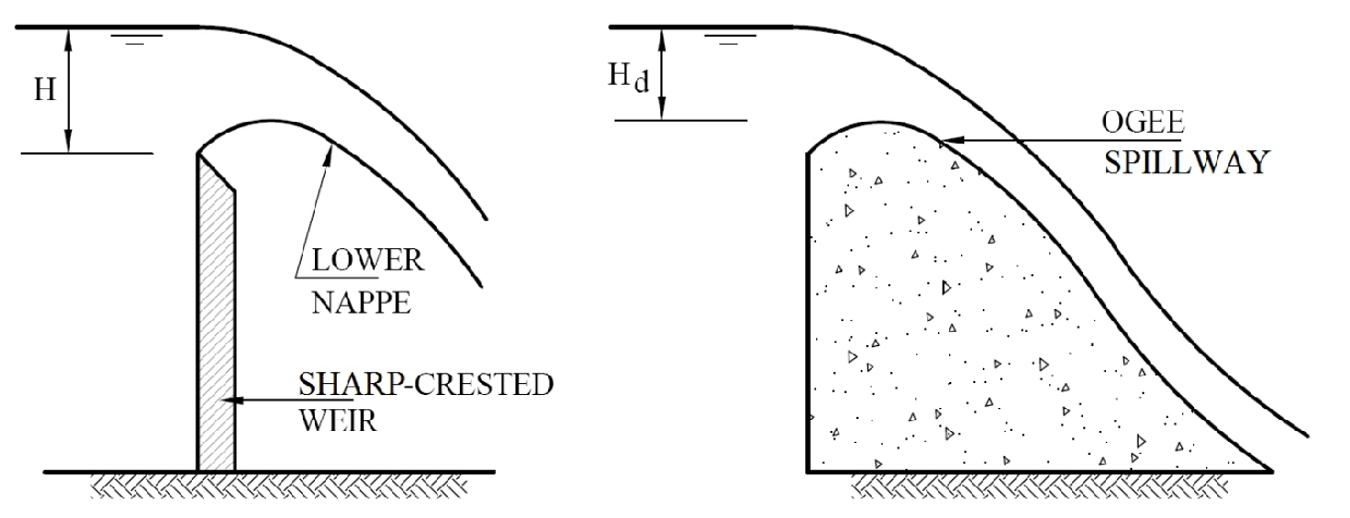
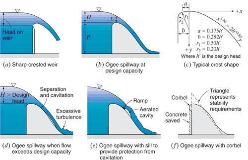
Energy dissipations are common in spillway systems, occurring primarily at the base. They mainly happen when these systems experience high velocity and form a stilling basin (Mojtahedi et al., 2020). Spillways are constructed based on their suitability to the site in question, among other factors. The different types of spillways are the drop spillway and the over fall and ogee. A drop spillway is designed so that the excess waterfalls on the downstream side of the hydraulic structure are vertical. It is mainly applied in low dams where the construction of a basin to form a small pool is involved. The small pool is primarily referred to as a water cushion, and its function is to dissipate energy. The overfall and ogee are more common, and they can be used on concrete or masonry dams because they have suitable crest lengths for the required discharge. This spillway has a controlled weir in the form of an S shape. The shape conforms to the profile of lower water nappe from a sharp-crested weir. The design head of the ogee crest stays at atmospheric pressure and becomes positive at the lower head, which leads to a backwater effect, and hence discharge is reduced. The pressure becomes negative at a higher head leading to an increase in discharge due to the backwater effect.

Methodology
The principle’s objective is the creation of a scale of 1:20 of a spillway containing a structure of a stilling basin. This is because the structures have been designed with the understanding of basic principles concerning spillways and stilling structures. Compared to the actual rivers and dams, the hydraulic structures are small, and their models are a replica of the expected behaviors of the actual structures (Cath et al., 2019). This prevents any disastrous accidents from occurring, which may lead to losses and potential loss of lives.
Different energy dissipaters or a combination can accompany the spillways. This should consider the amount of energy that needs to be dissipated and the level of control required downstream. The energy dissipaters should protect the downstream areas from erosion due to the reduction of the velocity of the flow to a limit that is acceptable. The flow to sub-critical conditions from the superficial may be achieved through a steep spillway. This involves the formation of a hydraulic jump to dissipate flow energy in large amounts. It is necessary since a lot of energy may be lost in a hydraulic jump created by steps, blocks, and other apparatus to increase turbulence. A common type of dissipater for dams and weirs is the stilling basin.
Diversion of incoming flow can be done using chute blocks and causes a lift from the floor. Stills may also be used at the end of the stilling basin to reduce the flow length and the speed of flow down (Wildenberg, 2021). The remaining velocity jet that may reach the end of the stilling basin is diffused. Obstruction of water flow is also done through baffle piers that allow kinetic energy dissipation. These are recommendations in designing small dams that need a slower steeper than expected.
Results
Table 1: Data from lab
The table above shows lab results of the values from the experimentation of the pressure heads along the spillway due to different conditions.

Discussion
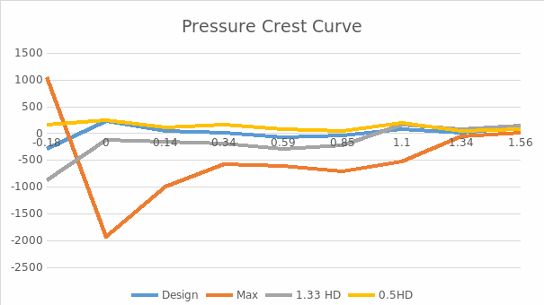
The measured flow rate was obtained to be 2.98 m3s-1m-1 of the 3m3s-1m-1 from the results of the laboratory model. A flow rate of 5.66m3s-1m-1 was obtained as the measurement of the discharge. The negligible differences achieved from the different scenarios prove that the tool used to design the spillway and the stilling basin was effective. A minimal error of 0.7% was achieved through the rating curve verified by the Froude scale when incorporated into the laboratory experiment. The pressure levels recorded were expected, with the lowest pressure from the max flow being -1940. Positive pressures were assigned to fewer discharges than the design discharge, while negative ones were assigned to discharge above the design discharge.
A downstream water depth of 2m and a stilling basin length of 16m were obtained. Calculations proved that the stilling basin had to be raised by 0.603m to achieve the desired 2m water tail; hence, it was insufficient to accommodate the hydraulic jump. Therefore, this would not be suitable for real-life application over a long period. If so, the hydraulic jump would lead to a large volume of energy, causing erosion on the riverbed (Debabeche, 2021). Observations showed that the hydraulic jump would move downstream due to the lowering of the tailgate and upstream due to the raisin of the tailgate.
The application of chute blocks enabled observation indifference of behavior in the water. They were placed in the basin where a hydraulic jump and dissipated energy were created once the water was crushed into them. This meant that the water could move the hydraulic jump in the basin. Such movement creates pressure that favors the working of the spillway system and the stilling basin in a manner that prevents flooding. Applications of these methods in real-life situations are likely to be costly; therefore, careful considerations must be made.
Conclusion
As proved from the design calculations, the Stilling basin had to be 16m in length. This length takes into consideration the hydraulic jump during the design discharge. Measurement of the stilling basin proved it to be around 1m reflecting a prototype model of 20m having the tailwater of 2m in depth. Results from the model test show that the stilling basin and the spillway design will perform effectively. The measured pressure head proved that the spillway was well designed since it did not exert pressure on the spillway. Model testing assured the theory of the design of the stilling basin due to the incorporation of the hydraulic jump.
Incorporation of the chute blocks and hydraulic jump into the design is likely to involve a lot of additional costs. The engineer should know which method to use to save on costs while maintaining efficiency at the same time. Scaled models are used during the design of spillways to predict the kind of conditions to be implemented to be effective. Hydraulic engineers continue to implement this strategy, saving them time while maintaining efficiency. The designs and the results should be cross-checked and proved to be correct as the results of the opposite may be hazardous. Necessary changes ought to be made on the designs before the commencement of construction activities. Knowing the test results gives the go-ahead for work to begin through building the actual structures.
References
Cath, T. Y., Hering, A. S., Holloway, R W., Newhart, K. B. (2019). Data-driven performance analyses of wastewater treatment plans: A review. Water Research 157, 498-513.
Debabeche, M., Hafanaoui, M. A. (2021). Numerical modeling of the hydraulic jump location using 2D Iber software. Modeling Earth Systems and Environment 7(3), 1939-1946.
Gayar, A. E. (2020). Impact assessment on water harvesting and valley dams. Int. J. Agric. Inven 5, 266-282.
Mojtahedi, A., Soori, N., Mohammadian, M. (2020). Energy dissipation evaluation for stepped spillway using a fuzzy inference system. SN Applied Sciences 2(8), 1-13.
Wildenberg, S. D., Valance, A., Roche, O. (2021). Experimental assessment of the effective friction at the base of granular chute flows on a smooth incline. Physical Review E 103(4), 042905.