The service life of an engine is determined by evaluating finite element structures in order to investigate temperature and stress parameters for a specified time period. In his research on life cycle of an engine.Broede argues that rotational speeds and engine intake are functions of time and assume a typical real flight mission with respect to the life consumption of the engine components. Broede further indicates that damage calculation show structure locations that have highest life consumption and forms foundation for declaring critical areas of structures that should be monitored. The stress in these areas is determined by the monitoring system and the temperatures are determined from structural points that forms a good approximate of thermal stresses at the specified critical areas. This is done by monitoring algorithms and should satisfy modeling of the heat conduction.
Pfoertner proposes determination of gas path temperatures computation of heat sources as this is a derivative of metal temperature development of the structure. This facilitates modeling that is based on approximated performance designs. The power function model is represented as T gas*=a+ b (N rot*) c where T gas* and N rot* are thermodynamically reduced gas temperature and rotational speed (that is normalized to International Standard Altitude conditions) and variables a, b and c are individual gas temperatures from calculation of design performance. If the temperature points of a compressor inlet and outlet temperatures Tgas1 represent Tgas2 are available and the temperature points consisting of several stages with a long extension in axial direction are considered, the linear combination of them will be T gas= (1-c).T gas; 1+c.Tgas2. This combination is used with different values of c which represent the corresponding points of the gas temperatures.
Harrison indicates that development of metal temperatures requires a discreet dynamical system that is derived from Fourier’s heat conduction operation by discretisation subject to the time and spatial coordinates. The temperatures in each point are calculated stepwise starting with an initial temperature distribution. The temperature at time step i follow from its value at the previous time step i-1. A leading temperature Tlead is assigned which depends on the selected gas temperature Tgas: Tlead (t) =Tlead(i-1)+a.(b.Tgas(i)-Tlead (i-1). The leading temperature Tlead and temperatures of at least three neighboring points Tj determines the increment of metal temperature of the considered point T(i)=T(i-1) +c.(Tlead(i) -T(i-1)+∑dj(Tj(i-1)-T(i-1). This implies that the change in metal temperature is directly proportional to the difference between gas heat transfer and the conductivity of the metal. The variables a, c, dj are functions of rotational speed N rot and are power functions of the form e+ f. (N rot/Nrot.ref) g with a given reference speed N rot.ref and constants e, f and g. A combination of speed, pressure and gas temperature can be used instead of dependency on the rotational speed N rot. The variable b depends on rotational speed and is calculated normally for about five selected speed valves conditionally to meet the steady state of metal temperatures for these speeds, the b values for other speeds are linearly interpolative. The more or less remote gas path temperature T gas represents the heat transfer from the gas to the metal point and is delayed twice in the time successfully, by effect of the parameters a and c and is distorted by b.
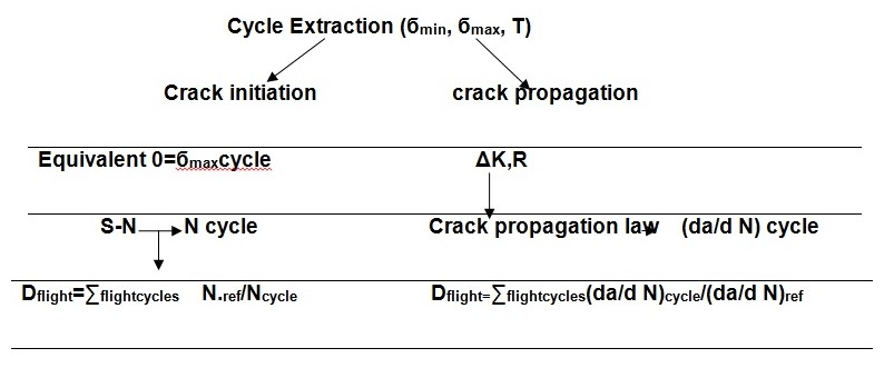
The total amount of the assembly, centrifugal and thermal temperatures gives the stresses for each specified area and this is represented by the equation b =Co+Ccf.Nrot2+∑cj.Tj where co, ccf and cj are derivatives of minimized maximum stress errors evaluated on the basis of metal temperature for the speed. Broede and Kohl point out that in life usage monitoring or consumption assessment, the released life of an engine component is formulated in terms of maximum allowed number of reference cycles. The relative cyclic damage of an arbitrarily given stress cycle is conveniently defined by the ratio of damage of the cycle to the damage due to the reference cycle. D cycles = (damage of cycles)/ (damage of reference cycle) and is expressed in units of one reference cycle. If Ncycle denotes the total number of given stress cycle leading to crack initiation, the damage of one reference cycle is denoted by 1/Nref. The relative cyclic damage for the crack initiation phase will be Dcycle=Nref/Ncycle.
In crack propagation rate (da/dN)cycle, damage of the reference cycle by (da/dN)ref, yielding the relative cyclic damage Dcycle= (da/dN)cycle/(da/dN)ref. In the concept of crack initiation life, the damage accumulation process is assumed to be linear and damage increments are independent from the current state of accumulated damage then the relative cyclic damage values of each extracted cycle are added up. In crack propagation, all stress cycles are converted into stress intensifying factors using the equation K(a)=g(a).bcriticalarea+Kadd(a). The crack propagation law is used to calculate increments using stress intensity factor range K/R-ratio and temperature. (Fig 1).The total damages of the run engine are added once the engine is switched off. The time utility is dependent on the time difference between start of the engine and take off as well as landing and shut down of the engine.
Bibliography
Broede, J. & Kohl, M. “Aero Engine Life Usage Monitoring Including Safe Crack Propation.” Proceedings of the 2nd International Workshop on Structural Health Monitoring, Stanford University, Stanford, CA. 1999.
Broede, J. Engine Life Consumption Monitoring Program for RB199 Integrated in on-Board Life Monitoring System. Quebec: AGARD CP 448, 1988.
Harrison, G. “Translation of Service Usage into Component Life Consumption.” Recommended Practices for Monitoring Gas Turbine Engine Life Consumption RTO Technical Report 28(RTO-TR-28,AC/323/(AVT)TP/22. 2000.
Pfoertner, H. “Extension of the Usable Engine Life by Modelling and Monitoring.” Aging Aircraft Fleets: Structural and Other System Aspects. in Sofia (Bulgaria), RTO-EN-015, 2001: RTO Lecture Series 218 bis.
