To investigate the differences between an open loop and closed loop motor speed control in the presence of mechanical load.
Apparatus
- U-151 Dual attenuator
- U-152 Summing amplifier
- U-153 Pre-amplifier (gain: 20 dB)
- U-154 Motor driver amplifier (10 Watts)
- U-155 Tacho amplifier unit • U-156 DC power supply (±15V, 0.2A and motor power)
- U-157 Potentiometer
- U-159 Tachometer (FS 4000 RPM)
- U-161 Servo motor (Motor: 12V, 4.5W | Tacho generator: Approx. 3Vp-p/4000RPM)
- U-163 Magnet Brake
- Patch chords
Theoretical Background
When a motor is used to make mechanical force, it is usually expected to keep going at the same speed even if the load changes. An example of an automatic regulator is a closed-loop speed control system, in which the motor’s actual speed is compared to the target value to provide an error signal output. When a voltage discrepancy between actual and desired speed is discovered, the signal is enhanced and sent back to the control circuit. This process of self-correction will continue until the erroneous voltage is zero (Li et al., 2019). After the desired speed is reached, the actual speed of the motor will remain constant at that level. All the systems constructed up to this point in the experiments are considered open loop systems, in contrast to the closed -loop system. A closed-loop motor control is a method employed to govern the motor’s output (Devasia, 2023). A sensor continuously evaluates the output response of the motor, and the sensor output regulates the input by acting as feedback. Fig.1 and 2 are visual representations of the key concepts, which describe the contrast between open-loop and closed-loop systems.
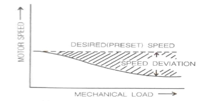
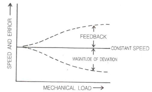
As can be seen in Figures 1-2, a closed-loop system is far more effective in preserving a steady speed in the face of changing loads than an open-loop system. The “deadband” effect may be avoided in a closed-loop system by amplifying the error signal to a sufficient level. Error signals are thus amplified before being sent to the servo driver’s input (U-154). Having the feedback signal remain 1800 out of phase with the reference signal is also crucial for constant regulation.
Block Diagram
Schematic Diagram
Procedure
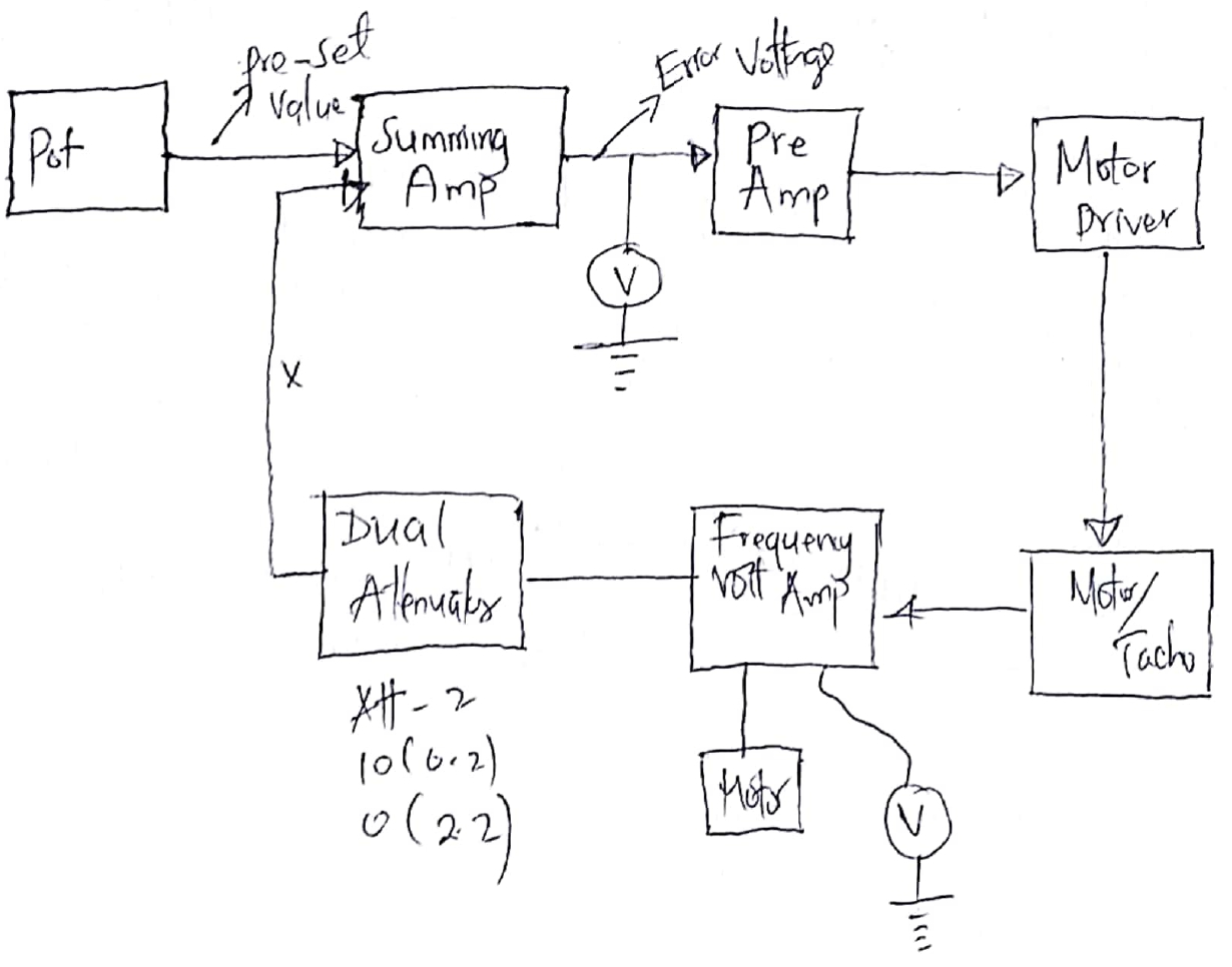
Referring to the connection diagram and schematic diagram, the required modules were arranged and connected together. The selector switch of Summing Amp U-152 was set to “a” and a flywheel was then connected to U-161 (20g). The voltmeters were then connected at the output of summing amplifier (U-152) and tacho amplifier unit (U-155) for reading the error voltage and the motor output voltage respectively. The ATT-2 of the U-151 was then set to “10” to prevent Tacho output from entering the system and the ATT-1 set to “5”. The power of U-156 was then turned on while adjusting the U-157 to obtain about one half of the maximum speed. This is the same as setting for 2500 RPM on U-159 meter. An electronic brake U-163 was attached, and with the brake’s setting increased by one notch at a time, the RPM reading were recorded at each setting and tabled as shown in the table below (see Table 1). Subsequently, the error voltage at each brake setting were measured and recorded along the RPM readings as indicated in the table below (see Table 1).
In the second set of steps, ATT-2 of U-151 was set to “5” with adjustment of the U-157 to obtain the same speed as in Step 6 (around 2500 RPM) where brake U-163 was attached. The speed and error voltage at different brake points were then measured and the data points on the graph plotted as indicated in Fig. 5-8. The ATT-2 setting was then changed to “0” and U-157 adjusted to obtain 2500 RPM. The speed and error voltage at each brake setting were then measured and the data plotted on a chart as indicated below (see Fig. 5-8). Finally, the results between Steps 4-8 and Steps 9-12 were compared since the loop was closed for steps 9 through 12, starting from the point at which the ATT-2 of U-151 was set to “5”.
Measurements
Table 1: Measurements of Error Voltage and RPM for both open and closed Loop Configuration
Graphs
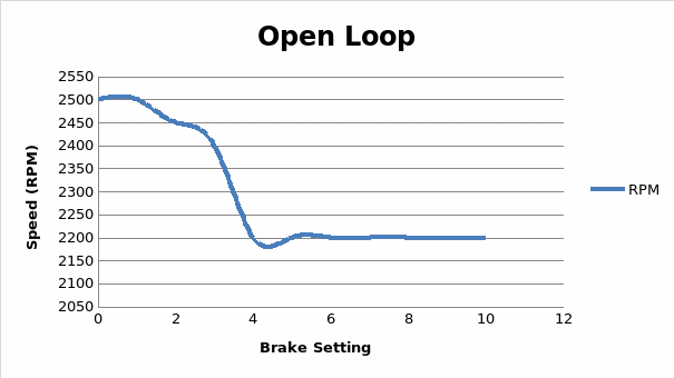
From the graph above, when attenuator gain rises, Kc likewise increases, resulting in a rise in applied voltage. Hence, motor angular velocity will accelerate. While the attenuator gain stays unchanged, the brake scale increases and the motor’s angular speed drops. The rationale is the same as in closed loop system. When the brake scale rises, the motor angular speed drops.
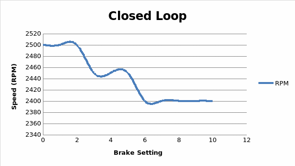
From the graph, when the brake scale position increases, motors angular speed drops, as seen by the graph. This is due to the analogous viscous coefficient mirrored at the motor shaft, which increases as the braking scale (viscous load) positively changes. In accordance with the transfer function’s equations 11, when the brake position rises, the motor’s speed of rotation will eventually decrease (Schmidt et al., 2019).
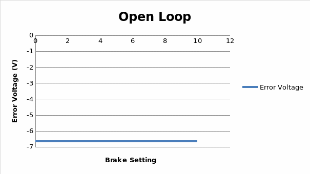
From the above diagram, it is evident from the data that increasing the disturbance torque load (T L) by adjusting the brake position with the magnetic brake does not change the error voltage from the desired output by a wide margin in an open-loop system. In this case, the output (error voltage) does not interfere with the control action of the system.
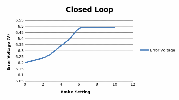
Figure 8 displays experimental results for the brake scale setting in a closed-loop control system against error voltage. It demonstrates that, for a given gain, the total settling time and rising time reduce with increasing brake scale setting. The voltages are optimized by the system utilizing the gain available after the addition of the gain loop, which acts like a multiplier. Hence, using the identical multiplier, the system will achieve steady state faster as the error grows due to a greater brake scale position.
Conclusion
Open-loop systems are fundamentally distinct from closed-loop systems in that the former can self-correct whereas the latter cannot. Thus, open-loop systems are sometimes called non-feedback controls, while closed-loop systems are often known as control mechanisms with feedback. Since open loop control methods lack output measurement and feedback, their reactions are rapid. Owing to the existence of feedback, the response time of the closed loop control system is sluggish. Open-loop control systems are less dependable. Therefore, using a closed-loop control system is secure.
Questions & Answers
Explain the schematic diagram of this experiment
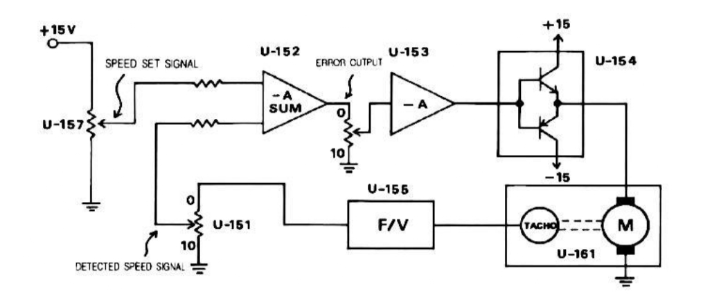
Fig. 4 shows a representation of a schematic and simplified speed/position control system for a direct current (DC) motor that is operated by means of the armature. When ATT-2 of U-151 is set to “5”, closed-loop speed control is activated. A Tacho generator is used to generate a voltage that is inversely proportional to the output speed. An operational amplifier connected as a summer subtracts this from the input to arrive at the final value. A servo-output amplifier’s is utilized to power the motor, which in turn amplifies the fault (Karimi-Ghartemani, 2022). The motor cannot be driven without the servo-output amplifier’s power, which consists of voltage and current. The permanent magnet configuration generates eddy currents, which in turn impart a torque on the load that is roughly proportional to the disc’s rotational speed owing to the load’s viscosity (Gambhire et al., 2020). The system is stable and first order, with the output trailing the input. A closed-loop position control system is achieved by looping the output shaft position back into the input.
Why did the error voltage not change when the ATT-2 of the U-151 was set to 10?
Setting the ATT-2 of the U-151 to 10 prevented Tacho from entering the open-loop control system, thus the error voltage does not change.
How was the reduction in motor speed due to a load was being compensated by the closed loop configuration of the set-up?
Real-time position and stator current feedback are used by closed-loop control to adjust the speed regulator, the current processor, and the inverter’s switching speed. This guarantees that the rectified three-phase voltage supply (which operates the motor) rectifies the feedback divergence of the motor from the target value.
Reference List
Devasia, A. (2023) An introduction to types of closed-loop motor, Control. Web.
Gambhire, S.J. et al. (2020) “Review of sliding mode based control techniques for control system applications,” International Journal of Dynamics and Control, 9(1), pp. 363–378. Web.
Karimi-Ghartemani, M. (2022) Modeling and control of Modern Electrical Energy Systems. Hoboken, NJ: Wiley-IEEE Press.
Li, X. et al. (2019) “Characteristics and performances of a small-scale model of the closed-circuit multiple controlled fan wind tunnel”, Review of Scientific Instruments, 90(4), p.045104. Web.
Schmidt, R.A. et al. (2019) Motor control and learning: A behavioral emphasis. 6th edn. Champaign, IL: Human Kinetics.