Introduction
Using mathematical calculations to analyze an electrical circuit is a critical step in performance analysis and risk assessment for the circuit in use, allowing an understanding of current flow characteristics and weaknesses potentially leading to circuit vulnerabilities. One such object of interest is the daylight sensor switch, a device that uses a photoresistor to detect ambient light levels and automatically adjusts lighting accordingly. Obviously, for normal functionality of such a device, it is necessary to ensure that a stable voltage is supplied to the sensor, which means that the circuit must be able to transform the AC voltage into a regulated DC voltage with minimal loss and noise.
The present research project includes building a visual model of AC-DC Regulated Power Supply, performing calculations with demonstration of each step, and discussing potential advantages and vulnerabilities of the built circuit. Thus, the main objective of this project is to design and implement a circuit that can efficiently convert the incoming AC voltage to a regulated DC voltage of 9V AC/DC 50mA for sensor use. The successful completion of this project is expected to theoretically model a simple and efficient regulated AC/DC voltage source that will provide an energy efficient and convenient lighting control solution. The project will also provide valuable information and experience in circuit design and implementation, making it informative and useful for training for students and engineers interested in these fields.
Electrical Circuit Diagram
The electrical AC-DC Regulated Power Supply shown in Figure 1 was used for the work in this report. AC power is passed through a fuse, which serves to protect the circuit from damage, and then passed through a transformer, which is used to reduce the 230 V input voltage level to a value suitable for the circuit. The converted AC current is passed through a rectifier made from a combination of 0.7 V diodes, which converts the AC power to DC power. The rectifier output is passed through a filter, which smooths out the ripple in the DC output to a maximum variation not exceeding 100 mV. Finally, the filtered dc output signal is passed through a fixed voltage regulator, which maintains a constant output voltage despite input voltage fluctuations or load changes. Thus, the circuit shown below allows the input voltage of 230 V to be transformed to an output voltage of 9 V with a maximum current of 50 mA.

Circuit Calculation
Assumptions on known data:
- Input voltage: 230 V RMS
- Input Frequency AC: 50 Hz
- Output current: 50 mA
- Output Voltage: 9 V
- Maximum output ripple: 100 mV
To select the transformer, it must be considered that the output voltage is 9 V, so the transformer must be able to reduce the input voltage to at least this value. However, between transformer and regulator there is also a rectifier, which has its own voltage drop value of 0.7 V; therefore, this value must be compensated. One of the classic voltage values for the transformer is 24V RMS, so this is the value that will be used. The transformer voltage value allows to calculate the peak voltage:

To select diodes for a bridge circuit, consider that the maximum secondary voltage of the transformer is 24V RMS and the output current is 50 mA. To determine the voltage on the bridge circuit, you need to refer to equation:

For further work, it is necessary to designate the directions of currents that are implied. Fig. 2 shows these vectors, and additionally indicates the directions that were used to calculate the voltages.

Now, using the Kirchhoff equations, you can calculate the currents in the circuit as shown in equations:

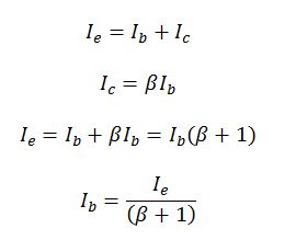
Given the known value of IE (IE = 50 mA) and Beta (β=63 for BD 139), the current Ib is 0.78 mA, as shown in the equation:

The value of currents IR, Ic, and IL can also be determined from the Kirchhoff equation:

It is also necessary to calculate the voltage value on the circuit section with Zener, as shown in the equation (11):

Now that the values of voltage Vz and peak voltage Vc are known, it is easy to determine the voltage value on the resistor (12)

Knowing the voltage value of the resistor, you can determine the resistance value, as shown in the equation (13):

Finally, it is now possible to determine the capacitance of a polarized capacitor:

Thus, based on all calculations, before simulating the circuit in LushProjects it is necessary to postulate known and received values:
- Transformer: ratio is 0.07379
- Diodes: 0.7 V
- Capacitor: 7 mF
- Resistor: 1.1k Ω
- Zener diode: 9.7 V (∆V = 100 mV)
- Regulator: beta is 63
Modeling
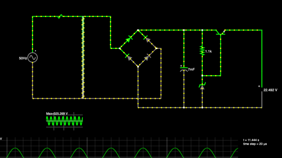
The values used were plotted on a schematic in LushProjects, the visualization of which is shown in Fig. 3.

Conclusion
In the present work an attempt was made to simulate a circuit, AC-DC Regulated Power Supply, lowering the input voltage 230RMS. Calculations and visualizations of the simulation are demonstrated in the paper. It was determined that the model was capable of lowering the circuit voltage to 22.5V.
References
- John. “Light sensor switch circuit: A guideline in building your sensor circuit.” OurPCB. Web.
- L. Xiong, X. Liu, Y. Liu and F. Zhuo, “Modeling and stability issues of voltage-source converter dominated power systems: A review,” CSEE JPES, vol. 8, no. 6, pp. 1530-1549, 2022.
- Jaycar. “24V, 72VA, 3A — single winding — Type 2158 transformer.” Jaycar. Web.