Abstract
The purpose of this study is to discover the composite action of bondek slabs by studying laboratory experiments on the behavior of composite material under the action of different forces.
The results are used to perform deflection calculations which provide analytical results that have short term and long-term implications on the design and behavior of composite materials, used to construct structural components and systems. The study investigates the behavior of composite materials at the points of interaction with the composite materials to understand the effect caused by the forces of shear stress, shear strain, flexural failure, and other forces that act on structural systems. That is in addition to the study of the thermal effects on the mechanical, frictional, and chemical behavior of composite materials. The finite element method, PSC, and FRP methods are used to compare experimental, theoretical, and industry standard values to determine the most appropriate design factors for composite slabs. The values must be compliant with the Australian codes and standards and those of other countries that have been deemed suitable for designing composite slabs.
Notations
- Es = the steel sheet modulus of elasticity
- Ey = the vertical spring’s stiffness in the finite element model
- F1 = defection caused by the rotation of the concrete block
- F2 = deflection caused by the bending sheeting
- Fc,cub= deflection measurement at the center of the specimen
- Is = the movement of inertial due to the steel sheet
- Ls = the length of the steel span
- Ms = moment due to the steel sheet
- Pmea = external load used in the test
- Pc = the load’s calculated value
- T = tension caused by the
- Tflow = the shear flow that is normalized according to line of indentation
- Z = the level arm
Introduction
A composite bondek slab is made of cold profiled steel sheeting or steel deck and ordinary structural concrete. According to Abdullah and Easterling (2003, p.34), Abdullah and Easterling (2007, p.5) and other different authors, composite slabs are characterized by the existence of a bonding action at the interface of the composite materials that is produced by the action of mechanical interlock, friction, and chemical forces. Abdullah and Easterling (2007, p.45) argue that because different researchers have established different results on the behavior and action of composite materials, different methods of evaluating and analyzing the composite action of the bondek slabs have been developed to understand the relationship and action of the forces acting at the points of contact between the materials. Extensive research contributions and experiments conducted by An (1993, p. 67), Ayoub and Filippou (2000, p.45), Bode, Minas, and Sauerborn (1996, p. 12), Chen, Shi and Qiu (2011, p.90) on the stress and strain properties of composite materials show that the stress and strain properties of bondek composite slabs are governed by the forces that act on the points of interaction between the concrete and the steel deck.
Abdullah and Samuel Easterling (2009, p.4) have shown that studying the composite action of bondek slabs when exposed to dynamic and static loads is an important milestone in the construction industry because it provides knowledge on the behavior of composite slabs at the points of interaction and provides researchers with the ability to design the best composite materials suitable for use in the construction industry and in situations where such materials are subjected repeatedly applied loads. The research findings lead to the design and development of composite materials with improved vertical and horizontal shear capacities to resist forces that cause excessive deflections which can lead to the damage of the composite concrete slabs.
The resulting composite materials have improved properties which are gained when concrete and other construction materials are combined to make composite materials with the right mechanical, chemical, and thermal properties which are suitable for construction purposes. A report by Ayoub (2012,p.5) shows that different researchers have established similar results based on different studies on the behavior of bondek slabs based on different types of tests. Other investigations conducted by researchers, institutions, industry, and university professors to determine the behavior and action of composite slabs under the action of vertical and horizontal shear forces show some variations with industry and experimental results. Different standards used include the “American Society for Testing and Materials (ASTM)” which defines technical requirements for building and material standards. The technical standards are classified into standard specifications, standard classifications, standard methods, and standard guides.
Here, Ayoub (2005,p.453) argues in accordance with the ASTM C31/C31M-00e1 (2002 p.37) codes used for testing different mechanical properties, which reveal the behavior of composite slabs under different test conditions and provide data on the appropriateness of the composite materials for use in the building industry. The behavioral characteristics of the bondek slabs under investigations have to be consistent with acceptable buildings standards. To determine the suitability of the bondek slabs for the building industry and consistence with the building standards and Acts, a number of requirement tests have been conducted. According to Ayoub (2005, p.387; ASTM C39/39M-01 2002, p.3), Benedetti and Mangoni (2007, p.223), and Bode and Dauwel (1999, p.10), compliance tests include chemical adhesion, mechanical interlock, and friction tests in addition. In that context, different researchers have developed different concepts in the area of analyzing the composite action of bondek slabs against standards that make it suitable for use in the construction industry. According to the American Society of Civil Engineers (ASCE) (1992, p.5), the type of bond or bonding characteristics between the composite materials has a significant effect on the performance and action of the composite bondek material. Lateral pressure is one type of effect that has performance implications on the performance of composite materials and is a critical factor to consider when steel decking.
It is important to note that research has established a common ground to agree on the mechanism of the composite action which influences the bonding between steel and concrete. Iit is important to base the study on empirical evidence which has been developed by researchers to try to understand the composite action of bondek slabs when subjected to mechanical forces which cause composite slabs to deflect. This study focuses on the composite action of bondek slabs under different prevailing conditions in the test environment and provides analytical calculations, a critical approach to determining the behavior of the materials and the applicability of the materials in the building industry, while evaluating the compliance of the materials to the Australian building codes and standards.
Aims
The aim of this report is to discover and explore information on the composite action of bondek slabs as well as identity and calculate the deflection for this property for both short and long-term measures, applying it wherever possible within the construction industry for structural purposes.
Goals
- Understand how composite action of bondek slabs works by utilising deflection calculations for both short and long-term usage
- Understanding the composite action of bondek slabs by designing an experiment that aims to measure and find out how composite action of bondek slabs can be tested; incorporating the calculations required for deflection
- To investigate the method of design procedure for bondek slabs that are to be placed in a system developed with composite materials, including the design material, specifications and types of extra material to be used (i.e. reinforcement, shear connectors, sheeting, concrete, etc.)
- Research different case studies and experiments that university professors have constructed to determine the composite action of bondek slabs and measuring/calculating deflection for short and long-term usage
- Applications of bondek slabs to PSC and FRP
- Comparison between computer-based calculation (for deflection of bondek slabs) and industrial theory methods
Objectives
The main objective is to study and analyse the composite action of bondek slabs based on deflection calculations (short and long-term).
Definitions
Composite slab-two or more materials combined with enhanced mechanical properties for engineering purposes
Shear stress-The action of coplanar forces on cross sectional part of a material subject to stress
- T-Tensional force
- T-deck thickness
- Nc-Concrete compressive force
- Mr-Bending moment
- L-length of span
- K-reduction factor
- S-slope of shear bond regression line b-width of the composite material
- D-effective depth of the composite material
History
The mechanical and chemical properties of composite bondek slabs derived from the action of forces created because of the bonding action produced by the composite materials have been studied for many years. Research shows that mechanical interlock, frictional forces between the composite materials and chemical actions create the boding action between the composite materials. Vinson and Sierakowski (2008, p.1) show that the ability to resist the action of the forces on the composite materials, makes the materials suitable for use in the construction industry. A study by Vinson and Sierakowski (2008, p.1) shows that history has documentary evidence of the process of combining different materials to form a new composite material with enhanced chemical and mechanical properties, making the new material suitable for different applications. According to Vinson and Sierakowski (2008, p.1), the ancient Israelites used to combine straw and other materials to produce a material with better structural integrity.
A similar case applies to the ancient Japanese. According to a survey by Johnson (1994, p. 2-4), the three elements which form the basis of the design of composite concrete slabs, which characterize the mechanical and physical properties of bondek slabs, include concrete, steel deck and reinforcement. Studies by Patrick and Poh (1990, p.34) show different contributions research had made on the development of composite materials based on historical knowledge of composite materials. Patrick and Poh (1990, p.34) argue that the mechanical properties and behavior of composite materials were investigated based on extensive mechanical, chemical, and thermal tests, which yielded different types of data and which contributed to the creation of standards to adhere to when preparing composite slabs. According to the Australian Standard for Concrete Structures AS3600, the properties gained during the design and construction process of the bondek slabs provides the composite material with suitable mechanical properties and capabilities for use in construction purposes. In this case, the steel deck that is developed using bondek slabs provides a formwork upon which concrete slabs can be placed and reinforced with cement.
The cement is allowed to cure to acquire the required mechanical properties. Patrick and Poh (1990, p.34), Patrick and Bridge (1994, p. 349), Patrick (2004, p34) and other authors with similar investigations into the history and behavior of composite slabs argue that such intensive and extensive investigations yield valuable data incorporated into the creation of different standards. According to the S2327.1-2003, the Australian standard which provides guidelines for designing composite materials for serviceability, based on allowable defection capabilities, influences the design and ultimate performance of the composite slabs during and after construction (Sakr & Sakla 2008, p.34). According to the Australian standards and research findings, the composite materials used in the construction industry are subjected to a wide range of deflection forces. The AS/NZS 2327 provides guidelines and standards for the design of composite slabs covering the ductility and mechanical strength of the slabs, columns and beams according to section two, three, and four of the standards respectively (Australian Steel Institute (ASI) 2009, p.9).
A comprehensive review by Schuster (1973, p. 45) and later by Sakr & Sakla (2009, p. 2988) and Smitha and Kumar (2013, p.72) shows that the prescribed codes and standards result from different tests conducted to determine the behavior of composite slabs when operating under different shear strain and stress forces. Research shows that some tests do not provide satisfactory results, which necessitate the need for additional tests to be conducted to verify results obtained from stress/strain tests. In addition, similar views were expressed by Schuster (1970, p. 560) and Valipour and Bradford (2009, p. 9) that prior tests including the stress/strain tests yield desirable results showing the need to conduct full-scale tests. The goal was to exhaustively examine to accurately determine the behavior of composite concrete slabs and associated steel strength. Schuster (1970, p. 560) and Valipour and Bradford (2009, p. 9) argue that to conduct the tests, it was necessary to include the basic elements required to fulfill the requirements for conducting the tests.
Previous Tests
A detailed overview by Bode and Sauerborn (1992, p.12), Daniels and Crisinel (1993b , p.39), and Holomek,Karásek, Bajer, Barnat (2012, p.23) of previous tests conducted using conventional reinforced concrete slabs observed that when composite concrete slabs were exposed to different forces, the materials experienced three modes of failure. One mode of failure included in the study is flexural failure. To study flexural failure, Bajer, Barnat (2012, p.23) used the “Standard Practice for Construction and Inspection of Composite Slabs (ASCE)” Standards as the basis to design the data to use to investigate the behavior of the composite concrete slabs. According to observations, the requirement for failure to occur according to ASCE standards was the presence of a complete interaction between the steel and concrete slabs (Johnson 1994, p.34).
Here, flexural failure was in response to the action of loads acting on and over the reinforced section of the composite slab. The yield values obtained from the tests of the three failure modes proved that the approach was ineffective in providing reliable values for designing and developing composite slabs and to rely on such values could provide inappropriately designed composite slabs which were unsuitable for use in the construction industry. ASCE provides Standard for the Structural Design of Composite Slabs. The failure of the above method to provide reliable values for the design of composite slabs appropriate for the construction industry was based on comparing different values yielded when different full-scale slab tests were conducted. The main causes of the failures when the composite material was subjected to full-scale tests were discovered to lie in the weakness of the bond between the steel deck and the concrete, which was used in the construction of the test-cases (Nie, Cai & Wang 2005, p.530).
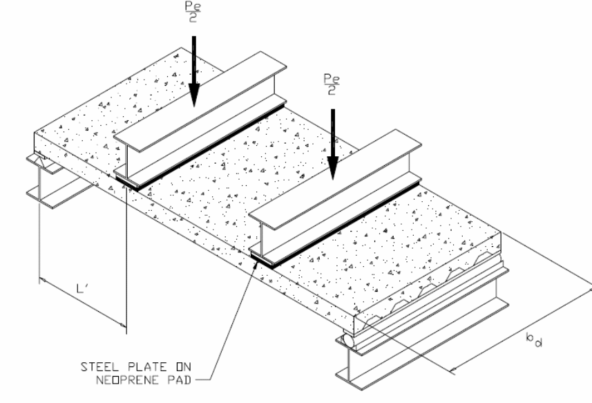
According to figure one above, the shear span is shown as ‘L’. The difference in the amount of load applied on the slab and the nature of concentration of the loads are defined by the type of shear span that occur on the slab. When conducting a test, it is possible to apply a uniform load on the slab. In that case, the shear span can be derived by calculating the area acted upon by the force and equating it with the load that is applied on a standard line of the applied load. Nie, Cai, Zhou and Li (2007, p.123) and Salari and Spacone (2001 p. 1234), conducted an analysis of the behavior of the bondek slabs when subjected to uniform loads and showed that failure at different points occurred because of the development of critical cracks near the third part of the length of the slab when subjected to vertical and horizontal loads. Numerical values obtained from the tests showed that failure of the composite slabs frequently occurred because of longitudinal shear stress. To appropriately analyze the behavior of the composite slabs at the interface boundary, research emphasized the importance of formulating mathematical expressions that could be used to provide accurate predictions of the strength of composite slabs because of the action of longitudinal forces. One of the pioneers who developed the first mathematical expression on the relationship between the strength of the bond between the composite materials and the shear forces was Schuster (1973, p.3) as illustrated below.

According to the experiment conducted by Schuster (1973), adopting the experimental value of the ultimate tensile strength of the concrete was the reason for the failure of the shear bond because practical values were exceeded in practice. However, the values yielded from the investigation were basically used to determine the composite strength of bondek slabs based on three parameters mentioned elsewhere. That included the percentage of steel used in the construction of test materials and the external shear ratio made with maximum values of the moment of the shear span. A graph was plotted to determine the regression analysis of the full-scale tests and results were analytically obtained by plotting a graph that is mathematically illustrated in the following expression.
The values obtained from the graph included the value of the slope of the graph, m, and the intercept, k that are critical in formulating the equation used to determine the strength of the shear bond. An analysis of the equation showed that a strong relationship existed between the strength of the bond, the depth of the slabs, and the shear span lengths. The variables used above can be rearranged to form the following equation.
If the values are substituted into the above equation, then the following results are obtained.

The shear bond strength can be calculated by substituting the value of Ls as follows.

On the other hand, the load design can be calculated using the PSC method as follows.

Research Areas
Another area of research to determine the properties of composite bondek slabs based on the action of transverse shear forces yielded the ultimate transverse shear expression. In the experiment, a regression analysis was done on the load test results to determine the values of m and k that consisted of the unknown coefficients in the equation. To ensure that a perfect regression line was created in the experiment, the test was conducted using two samples. The specimen consisted of a long thin span and a deep short span. Different parameters with different details were used in the study. The variations included the use of push out specimens, one way slab elements, two way slabs with the concentrated loads acting on them, continuous slab elements, supplementary reinforced elements, and two way slabs with diaphragms acting on them, and the use of the push off specimens. A number of important observations were made which resulted in the following discussions.
The result from the studies showed that the frictional resistance developed between the concrete and steel interface, the use of devices anchored to the composite material such as screws, the shape of the sheeting profile, and the embossments on the sheeting were the determining factors of the strength of the horizontal shear bond between the concrete and the steel profile. Several test methods have been developed to determine the strength of the composite slabs that is based on different profiles.
Composite Slab Design
Composite slabs provide enhanced engineering and mechanical properties suitable for construction purposes. That is in addition to the structural efficiency, safe construction methods, higher construction speeds, enhanced weight, and sustainable construction are some of the benefits of composite materials. Salari and Spacone (2001, p.823) and Schuster (1970, p.34) researched on the strength and behavior of composite materials that are used in the construction industry in accordance with the ASCE standard for the structural design of composite materials. The research established that standards are critical in determining the choice of materials to use for construction purposes. An area of critical importance is in the construction of floor slabs which are made of concrete and steel deck panels. The resulting materials combine the structural properties of formed steel and concrete to make composite slabs with several advantages.
Salari and Spacone (2001, p.825) shows that the benefits include the provision of a working platform that offers support during the construction process for wet concrete and other construction materials used in construction work,. That is in addition to the positive slab reinforcements gained from the use of steel decks, reducing steel additional requirements. However, the only steel is used to provide controlled conditions during shrinkage, temperature control, and to resist instances of negative bending (Siu & Su 2011, p.72). An additional benefit is the creation of distributed ducts that can be used in the provision of communication and mechanical services within the structure. It is also important to note that composite slabs can be used to aggregate the composite affects and actions on supporting steel floor beams and girders. One of the approaches used in the design of composite steel is the Limit Sate Design (Siu & Su 2011, p.74; Holomek, Karásek, Bajer & Barnat 2012 p.34; Valipour & Bradford (2009, p.34) and Veljkovic 1995, p.23; Veljkovic 1996a, p.23).
Bondek Floor Design
The design parameters include deflection limits of composite slabs, crack control, and span configurations. Other details can be included in the appendix. The output parameters include slab thickness which affects the long term and short term implications as discussed later. Other parameters covered include concrete cover, props, shrinkage, and the patterns on negative shrinkage.
Limit State Design
According to Widjaja and Easterling (1996, p.389), the limit state design is a method adopted and used in the design of composite concrete slabs. The method allows for the use of predetermined loads with slabs having specific strengths and subjected to different load conditions. Research by Zona and Ranzi (2011, p.23) based on the findings show that, the loads applied in the state limit design are specified based on the probability of event that the forces occur and the effect such loads could have on the performance of the composite slabs.
A study by Zona, Barbato and Conte (2008, p.986) showed that it was difficult to determine with enough accuracy the strength required to accommodate predetermined loads using probabilistic methods. However, results by Zona, Barbato and Conte (2008, p.986) agree that it is possible to make significant material savings. It is possible, according to research studies, to integrate safety into the structure of buildings while complying with existing codes and regulations. According to the National Building Code of Canada, the limit state design requires compliance to the following expression.
“Factor resistance>Effect of factored Loads”
The different variables in the above equation consist of the applied loads and include D, Q, T, and L that are defined as dead loads. The loads have a calculated resistance R factored into the equation. In the expression, the temperature that the deformation occurs is defined by T and the loads in the expression include Q, D and L (Bursi, Sun & Postal, 2005, p.68).
Bursi, Sun and Postal (2005, p.68) show that the above expression is appropriate using the variables or factors defined as, α which is the load factor that accounts for variable changes in load conditions, ץ is the factors that accounts for the combined loads except the extreme loads that may originate from other sources to prevent the probability of the event of extreme loads simultaneously. According to Bursi, Sun and Postal, (2005, p.68), the importance factor, ץ accounts for the probability of the event of a building collapsing because of the load that is applied by the occupants of the building. It is important to be certain that the properties of composite materials used in the construction of concrete slabs and the resistance factor take care of the material properties, measurements, and other uncertainties that contribute to the failure of the structural components. It is possible under the proposed method of design to have a probabilistic method of design, the second order moment approach, and other methods that will be discussed later in this section.
Probabilistic Approach
According to Chen and Shi (2011,p.1475), the probabilistic approach requires that any information made available is to be utilized appropriately in designing a composite structure because it factors different issues including the safety of the building and the occupants. The critical elements include: actual information provides about the mechanical properties such as the ability and extent to which the composite materials are able to resist the effect of shear stress when tangential forces are applied on the concrete slabs (Chen & Shi 2011, p.34). This information is critical because it provides a significant level of certainty to enable accurate decision making. However, because the information provided can be incomplete and factors different elements of uncertainty, the variability, incompleteness, and other variables which cannot be ascertained, the most realistic approach is to model the behavior of the composite material using probabilistic statistics.
Second Moment Approach
According to Chen and Shi (2011, p.1476), the second moment approach was developed to overcome and address the weaknesses identified with the probabilistic approach. A study by Dall’Asta and Zona ( 2004, p. 34) details the approach used to integrate the second order elements of the probabilistic approach into a mathematical model to measure the safety of composite construction concrete slabs consistent with the “Canadian Standards Association/National Building Code Joint Liaison Committee on Limit States Design”. In this study, Dall’Asta and Zona ( 2004, p. 34) affirm that this approach uses the “safety index” factor to measure the extent to which the composite material provides safety when used in the construction of buildings or other types of structures. In this case, time is an important element used to determine the safety of a structure. In the context of this research, when the safety index is valued at 1.0, the probability of failure is zero. Because the probability of failure is zero, the safety index is determined using the following procedure.
In the procedure, the effect of the applied load is S and has a probability distribution of fr. Here, the random variable, R, represents the strength of the material under investigations. The probability of failure occurs when all the values of S are greater than the values of R (Dall’Asta & Zona 2004, p.426). Here, S is a random variable due to the load effect and R is a random variable due to the material strength. When S is greater than R, the Z relation based on a lognormal is shown below.
Z = R-S
A mathematical approach is used based on numerical integration to determine the value of the probability that a certain event will occur such as the failure of the composite material. In this case, it is possible to determine with a significant degree of accuracy the probability of failure. A certain reliable approach is to use normal curves with probability distributions that are real. In the equation below, the variables are standards deviations. The variables used are shown below.
- s = standard deviation
- s = standard deviation
- R = standard deviation
- Z = normal distribution
- β = safety index
The normal curves can be obtained and the equation shown below used to determine the accuracy of the outcome of the distribution curves as shown below.

The standard deviation can be calculated using the mathematical equation shown below.
From the above equation, the safety index can be obtained by using the following formula.
The above numerical methods of determining the safety of a building developed which is using composite materials have some weaknesses. The weaknesses include the inability to determine with accuracy and specific materials suited to specific functions in the construction process, and the inability to determine with accuracy the appropriate mechanical properties which offer the best resistance to the loads acting on composite materials (Dall’Asta & Zona 2004, p.124).
FEM Analysis
Detailed research by Dall’Asta and Zona (2004, p.34) has shown that different structures require different approaches to designing the composite concrete to ensure reliable and efficient structures. A suitable solution for addressing the problem of creating appropriate composite materials for horizontal structures is the use of prepressed embossments on composite slabs. According to Dall’Asta and Zona (2002 p. 2217), the horizontal shear bearing capacity provides the basis for determining the most appropriate load bearing capacity of the composite slab. One approach used to investigate the behavior and suitability of the composite slabs for construction engineering is discussed here. In this case, the four point bending tests were conducted to determine the shear characteristics using a less expensive slip block tests (Erkmen & Saleh 2012, p. 55).
Modeling in Fire
According to the Australian standard and guidelines for construction materials, the standards provide specific guidelines and parameters to adhere to when designing construction materials to be resistant to heat. The standards specify the minimum specifications for thermal insulation for the “one way” spanning for room temperature, fire load, and transverse reinforcement.
Huang, Burgess and Plank (2004, p.323) shows through research studies that fire has a profound effect on the deflection properties of composite materials. That is because heat influences the behavior of the bonding membranes that exist between the concrete slab and steel deck. In this case, a research by Lim, Buchanan, Moss and Franssen (2004, p.1091) has validated that fire weakens the strength of the bond acting between the composite materials. Typically, fire is one of the factors that influence the behavior of composite slabs, with special emphasis on the membrane action of heat on the composite materials. In the above case, the many full-scale fire tests have been conducted to determine accurate values on the behavior of composite concrete slabs when exposed to different levels of heat. However, different numerical models, which are cost effective, have been developed for the purpose of determining the composite behavior of concrete slabs when exposed to heat. One of the tests with numerical simulations was FRACOF TEST. In the FRACOF TEST, the model used a number of variables which included steel columns and trapezoidal steel sheet. With the application of a uniformly acting load, two secondary beams were left without protection and exposed to changes in temperature (Benedetti & Mangoni 2007, 221). A graph of the deflection caused by the rise in temperature with time is shown below. The graph was plotted after values were taken from the results obtained from the experiment, as shown below.
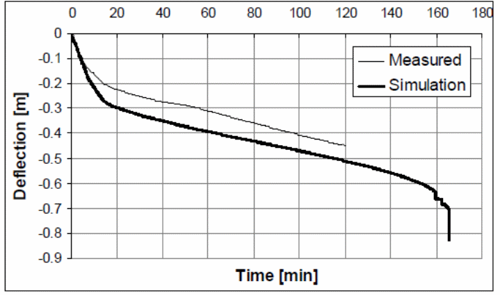
Different methods were used to simulate the tests and the results obtained were plotted on different graphs depending on the type of model in use.
Findings from the simulation models showed different factors influenced different behavioral characteristics of the composite materials used in the construction of the test structures under fire (Benedetti & Mangoni 2007, 221). In one of the tests, it was shown that the fire did not create any weakness on the vertical component of the composite material. However, other tests showed that composite structures with higher thickness values showed greater stability than thin structures. Another approach used to determine the behavior of composite slabs was to model the behavior of orthotropic composite slabs under the action of fire (Benedetti & Mangoni 2007, 221).
Orthotropic Composite Slabs
A software program developed by the University of Sheffield using a 3D model was used to analyze the effect of heat on the composite materials. Typically, the underlying concept is to use a non-linear approach to modeling the behavior of the composite material and the bending effect produced because of the application of heat (Bridge & Patrick 1996, p.41). The materials used included a beam with three nodes with a cross section area varying in size to allow for the application of different amounts of heat which generate different levels of stress and strain on the composite material. In the experiment, the cross section of the material is divided into a matrix segment for temperature variations. Results from the simulation using the software referred to as Vulcan is the matrix stress (Bridge & Patrick 1996, p.41). The stiffness matrix is calculated using the equation below.
The variables used include:
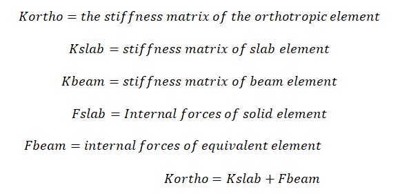
It is also possible to calculate the internal forces that are experienced when temperature changes occur as shown below.
The model that is created using the above variables is illustrated in the following diagram.
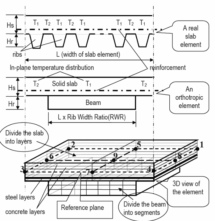
A non-uniform distribution of temperature within the structure shown above occurs because of the inclusion of ribs in the structure (Bridge & Patrick 1996, p.41). It is important to ensure that the distribution of heat within the body shown above is factored when determining the effect of temperature change on the stress and strain of the materials. From the above diagram, when the temperature measured along the line one is high, the temperature at the axis of line two symmetry is low (Fawzia & Fatima 2010, p.5). A graph of the changes in temperature at the integration points is shown below.
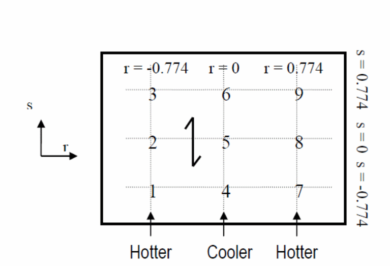
Best practices in the development of simulation models requires that the model be validated to ensure that it provides reliable results that can be translated into practical use and operate within the required safety standards (Bridge & Patrick 1996, p.41). Based on that, the above model is validated as follows.
Model Validation
The diagram below shows a TNO fire test conducted to validate the model (Cas, Bratina, Saje & Planinc, 2004, p.4890). In the following model, the test that was conducted in the Netherlands in 1996 consisted of simply supported composite concrete slabs at four corners. In the study, Cas, Bratina, Saje and Planinc (2004, p.4890) showed that the appropriate depth of the slabs to be 290 mm and the weight of the concrete was taken to be normal. In the test, the self-weight for the concrete slabs was 6.65KN/m2 and operated within the requirements of a typical load intensity of an office building. The results were in agreement with the facts established by Daniels and Crisinel (1993a, 16) and Huang, Burgess and Plank (2004, p.323) showing that the design was such that the assembly was required to provide a fire resistance that could last for 0 minutes with the composite concrete slab designed to extend the fire resistance by an additional 60 minutes (Huang, Burgess & Plank 2004, p.323).
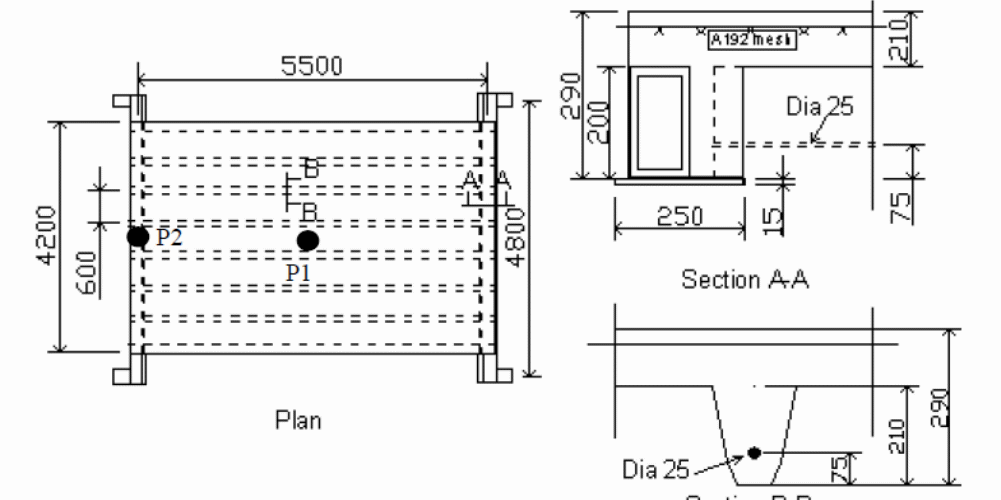
By plotting a graph of deflections which were caused by the action of changes in temperature in the vertical axis against time in the horizontal axis, the results were used to determine the temperature distributions within the structure. In this case, P1 and P2 are considered in the graph. A typical analysis consisting of u=outputs from the two models are shown in the graph above. Evidence from the graph shows that both graphs give different results (Huang, Burgess & Plank, 2004, p.323).
Another graph was plotted consisting of a BRANZ fire tests and the results are shown on the graph.
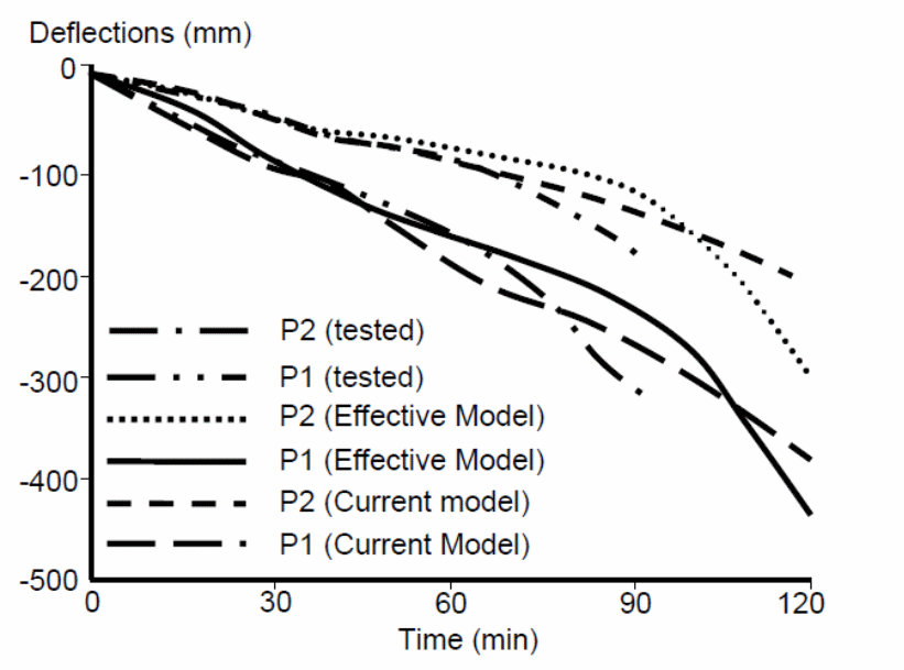
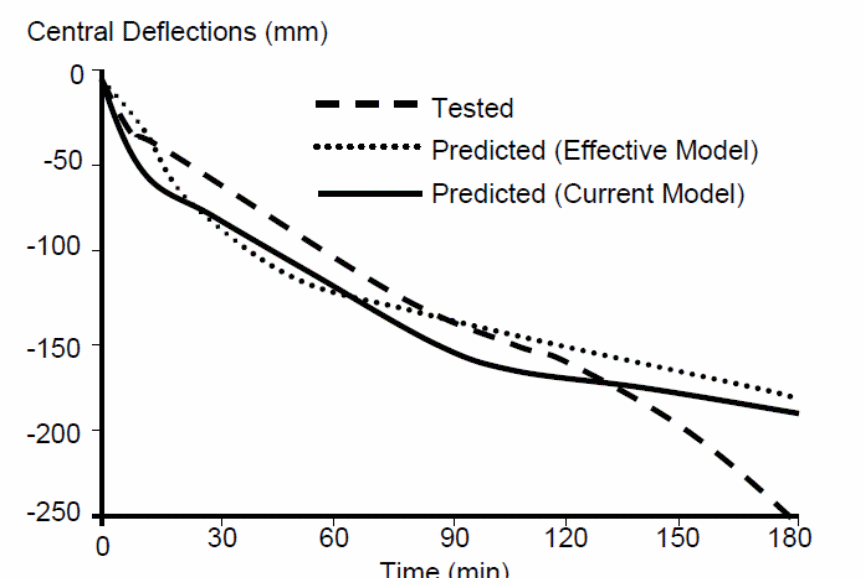
In this analytic, Sakr and Sakla (2008, p.1446) shows that the central deflections caused in the above graph and the previous graph shown significant differences between the results obtained from the models. It was possible to establish the reason for the differences in results obtained from both experiments (Sakr & Sakla 2009, p. 2988). The main reason, according to the study was because of the development of large cracks within the test slabs, the nature of the penetration of the flames within the slab, and the corner cracks that occurred while tests were conducted (Sakr & Sakla 2009, p. 2988).
Conclusions from the above studies show that the distribution of heat across composite slabs is non-uniform; creating a boundary condition that unevenly weakens the action between the composite materials (Sakr and Sakla 2009, p. 2988). It is important to note that the distribution of different elements within the material provides the composite materials with different thermal properties which influence the action of the forces between the elements of the composite materials. Based on the results from the models studied above, it is possible to accurately study the effect produced by different temperature changes on the mechanical properties of the composite materials, under uniform and non-uniform distributions of heat. Studies show that he shape of the steel deck has a strong influence on the distribution of heat and the resulting effect it produces on the composite material. However, an observed discrepancy between the actual performance and the experimental values is because of the different reinforcements done on both materials.
Model for the Mixing Theory of Composite Materials Model
The behavior of composite materials at the interface with other materials has been investigated and shown that the approach used to develop the materials influences the degree of resistance offered to shearing forces and the effect of the forces on the bonding action between the materials (Smitha & Kumar 2013, p.165). A study was conducted to determine the behavior of the materials used to make composite materials based on the mixing theory as illustrated below.
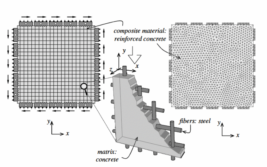
As shown in the above diagram, the composite material reinforced concrete has been modeled using a one dimensional model. In the model, an assumption of the axial behavior of the matrix fibers used in the study provides a perfect composite action of adherence between the materials (Smitha & Kumar 2013, p.165).
The Australian standards provide a detailed requirement for positive bending strengths that a composite material should adhere to, which is covered in clause 4.3.2.3 in EN 1994-1-1:2005. The design requirements for compliance are in the detailed design tables contained in the standards based on the partial shear connection theory (Fawzia & Fatima 2010, p.5).
The Mixing Theory
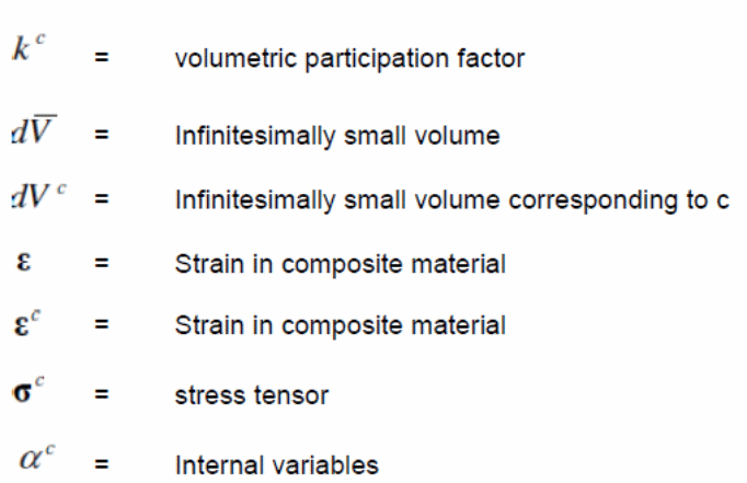
Smitha and Kumar (2013, p.165) extensively studied the mixing theory and showed how the theory provides the basis for studying the behavior of composite materials, According to Smitha and Kumar (2013, p.165) , the materials under investigations have similar mechanical properties which include strain properties, and the unit volume of the materials used in the investigation is lower than the volume of the composite material. In each case, the theory emphasizes the contribution of each material by volume to the behavior of the composite material to be based on the mechanical properties of each component. From the volumetric point of view, the participation is shown in the expression below.
In that case, the composite material and the component, in this case being the concrete slab are expressed in the relationship with the corresponding variables as shown.

In this theory, the strains that exist in the composite material are expressed as follows.

In the study, Smitha and Kumar (2013, p.165) shows that the mixing theory considers the composite materials to constitute free energy which results from the accumulated effect of the energy contributed by each component in the composite material (Smitha 7 Kumar 2013, p.165).
From an analytical approach, a stress tensor is created and is mathematically shown below. The formula can be modified to fit into different conditions that arise because of the application of different loads. The variables used in the equation are shown below (Tzaros, Mistakidis & Perdikaris 2010, p. 843; Fawzia & Fatima 2010, p.5).

Interaction Between the Bondek Sheets and Concrete
Studies by Spacone and El-Tawil (2004, p.23) and Abdullah and Easterling (2008, p.34) on the composite action of the bondek sheets that are placed beneath the main component to form an interaction between the concrete and the composite bondek sheet are determined by the longitudinal stiffness of the profile decking sheet. Shear cracks appear at the boundary between the concrete and the bondek steel sheet because of the existence of shear stress between the materials. Shear stress is caused by the application of cyclic loads which have a tangential effect on the points of interaction between the concrete and bondek sheets. The bonding action between the concrete and the bondek sheets is determined by the shape of the steel sheeting. The shear bond strength is determined by the surface treatment of the steel sheet, the steel sheet embossments, the shear bond resistance, and the resistance of the steel sheet to “peel-off failure” of the concrete at the point of interaction between the bondek sheet and the concrete. In addition, the force of friction between the bondek sheet and the concrete make significant contributions to the bonding action between the two materials.
A study of the long term and short term actions and implications on the performance of the bonding action between the bondek sheet and the concrete shows that the short term effect has a significant and more pronounced effect compared with the long term effect on the behavior of both materials at the boundary. An analysis of the observations shows that the cracks develop slowly and progressively as the forces are applied, as a longer term effect (Abdullah and Easterling 2008, p.29).
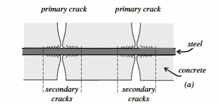
According to Abdullah and Easterling (2008, p.34), the partial composite action of the bondek sheet at the point of interaction leads to the loss of the bonding action and causes cracks to develop at the boundary between the materials, gradually causing end slip. A decrease in shear stress, which is the direct action of the long term application of forces, is observed (Sakr and Sakla (2008, p.1446).
A summary of the results shows that the action caused by the ultimate failure of the load shifts to the shorter span because of a shift to the midspan of the composite material at the point of interaction between the sheet and the concrete of the test component (Tzaros, Mistakidis & Perdikaris 2010, p. 843; Fawzia & Fatima 2010, p.5).
Failure
The Australian standards for making deflection calculations should be done according to clause 8.5.3 given in AS 3600:2009. Research has shown that the action of composite bondek slabs is based on three factors that influence the behavior of the slabs. According to Abdullah (2004, p.234), it includes the chemical and physical actions that exist between the steel sheeting and the concrete, the mechanical anchorage link that is influenced by the steel embossment, and the friction link between the interface materials. As shown in the graph below (figure 4), the load that is applied in the test experiment yields different values used to determine to a significant extent the deflection caused and the nature of the graph. Typically, each property is exhibited by the bondek slab and influences the behavior of the composite slab in relation to the different loads applied on the test material (Spacone & El-Tawil 2004, p.160).
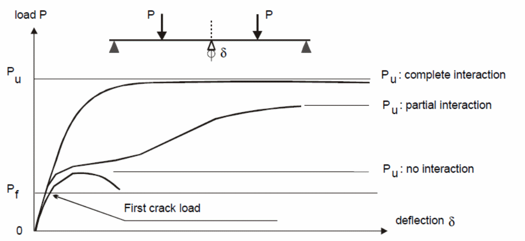
A typical example is the change that is observed to occur between 0 and Pf. Within this region, the chemical and physical bonding influences the composite action of the bondek slab and is dominated by the properties of steel and concrete. When the material yields to the action of additional loads, the mechanical anchorage links start to take effect causing the occurrence of micro slips. The connection existing between the concrete and the steel sheeting determines the kind of stiffness experienced here. In this case, the type of failure that occurs depends on the nature of the composite action of the steel and concrete (Spacone & El-Tawil 2004, p.160).
Failure Modes
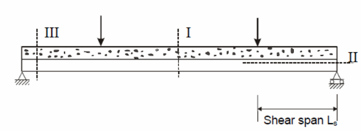
Spacone and El-Tawil (2004, p.150), Chen, Shi and Qiu (2011, p.234), and Erkmen, R & Attard, M 2011, p.1298) have shown that composite materials operate under three types of failures that are possible here. The first type of failure is the type I failure. In this case, the cause of type I failure is the sagging moment caused by the bending resistance of the slab defined by Mpl. Rd, which is described as the characteristic behavior of the slab to resist bending. This is the most critical type of failure experienced by composite slabs which have medium to high spans, with an interaction between steel and concrete very high (Spacone & El-Tawil 2004 p.150). The force of interaction between the concrete and the steel sheeting determines the resistance to failure due to the applied load. The other type of failure is type II failure. This type of failure is cause by longitudinal shear. When the load resistance that occurs between the concrete and the steel sheeting is reached, failure is experienced along the shear span Ls. On the other hand, the failure type III is caused by vertical shear. The “vertical shear is critical at the edge of the support section with slabs having short spans and operating under heavy loads” (Spacone & El-Tawil 2004 p.150).
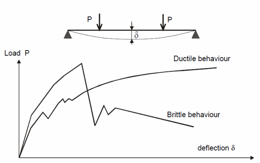
It is possible for a brittle material to fail because of the sudden application of force. However, when this type of failure occurs, it is difficult to determine the deformation caused on a brittle material because of the sudden application of loads. In a similar context, the application of a sudden force on ductile materials, it is possible for the deformation caused on ductile materials to be measured because of the application of any type of force. The graph below shows the behavior of ductile and brittle materials subjected to similar load conditions.
The Experiment
Inverted and normal positions of steel decks were used in an experiment conducted to determine the behavior of composite slabs. Observations are discussed below.
Phase One Result
It was observed that the entire specimen used in the first phase of the experiment experienced a shear bond failure. The points of failure were identified to be from the point of loading with major cracking observed to have developed from the shear span. In that case, the occurrence of end slips was recorded with vertical separation occurring before the application of any loads on the composite slabs. According to the Australian building standards, recommendations to control cracks are contained in the crack control AS 300:2009, clause 9.4.1. Recommendations for the minimum composite material property are detailed in this section for the purpose of providing guidelines on the size of materials for specific applications.
Deflection Tests
Experiments to investigate the effect of loads on the composite action of bondek slabs using full-size and elemental tests provide answers to the investigations on the effect of shear bond between the slabs and steel sheeting material. In this investigation, the performance of the bondek slabs is investigated to predict the actual strength of the bondek slabs when used in the construction of buildings and other structures (Holomek, Karásek, Bajer & Barnat 2012 p.34). In this study, consisting of two experiments, the first part of the experiments consisted of 1 specimens that were characterized by a deck profile of 75mm, a concrete thickness of 125 mm, 165 mm and 190 mm respectively, sheeting thickness of 1.5 mm, and a 560 mm, 660 mm and 760 mm shear span. The results of the tests were used to determine the web curling effects as illustrated in the figure below.

The support details for the tests are illustrated in the following figure.
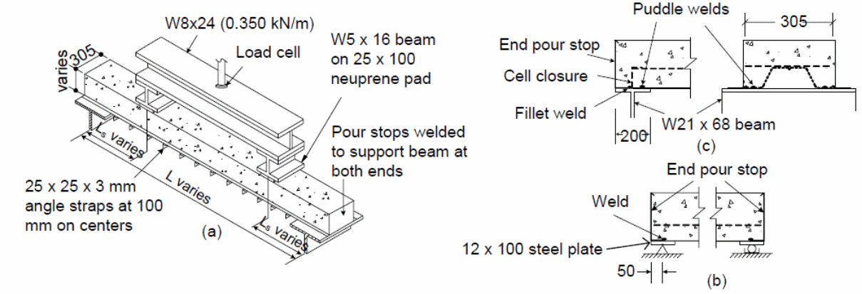
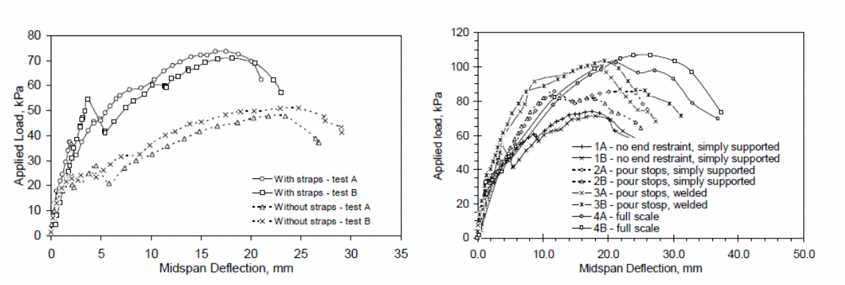
The results determined from the experiments showed that web curling was possible at the edges of the test specimens. An investigation into the cause of web curling was because of the overriding effect of concrete which led to the concrete to slip because of the bending effect that was caused by the forces that were produced because of the embossment of the web surface. The effect was a reduction on the effect of the horizontal shear resistance, with significant effect observed on the elemental specimen that as used in the investigation. The study further shoes that when the strapping space is increased; the vertical separation increased because of the lower strap strengths. Graphs detailing the effect of the strapping and the effect on the specimen with straps are shown below.

The above graphs show the effect of strapping on the elemental specimen and the effect caused by different end constraints.
In the graphs below, the effects of the applied load on the test specimen and the end slip is illustrated.
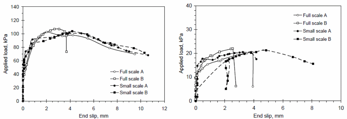
An analysis of the above results shows that web curling is only possible at the edge of the test material or concrete slab. In this case, the slipping of the concrete is the direct cause of web curling. The resulting effect is a reduction in the resistance that acts horizontally. It has also been shown that the size of the web influences to a significant extent the nature of web curling that occurs on the test materials. Research has shown that different constraints produce different effects on the behavior of the composite concrete slabs. The differences in the behavior of concrete provides the basis to argue that different loads when applied on different concrete slabs with different sizes produces different deflection effects on the materials.
Deflection When Reinforced with Materials
Vertical Resistance
It is possible to calculate the vertical resistance that occurs at the interface between the concrete and the steel sheeting when determining the composite action of bondek slabs. In this case, the study uses steel and concrete block in contact and at one point in the system. Typically, there is a vertical separation in the set-up and a point of contact at one point in the system. The vertical separation in this calculation is represented by Sy, with the vertical force determined by the following expression:
Long-term and Short-Term Impacts
A comparative study of the impact of long-term and short-term deflections based on deflection calculations shows that long-term deflections which result from creep because of excessive cracking are significantly higher than short-term deflections when studied on continuous beams. The problem with long-term deflections can be fixed by increasing the depth of the slab and thickening the slab to improve on the stiffness of the slab.
A study of the long-term behavior of simply supported beams using post-tensioned composite materials illustrated in the following figure shows has been studied and widely accepted in Australia.

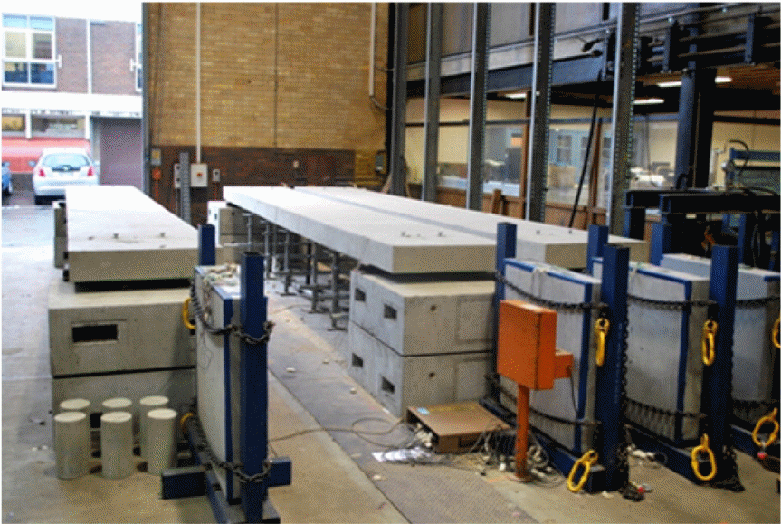
A series of long-term tests conducted by Ranzi, Al-Deen, Ambrogi, and Uy (2013, p.1-9) established the time-dependent behavior of post-tensioned composite solids and slabs yielded results for analytical and numerical modeling for 298 days, beginning the test at day 8, and the time-dependent deflections observe. Results for the time-dependent tests were plotted in the graphs shown below.
The experiment yielded the following results:
- The shrinkage due to moisture egress was significant
- Significant shrinkage occurred with time
- Free shrinkage was significant for the composite slabs with time
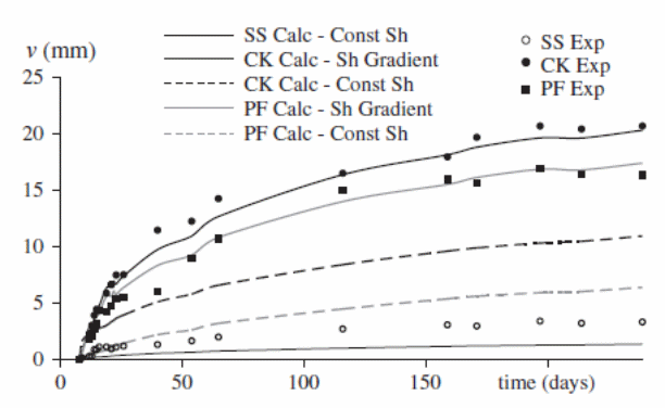
Differences in experimental and numerical results in the experiments are illustrated in the above graphs.
Serviceability load deflections
The following are short-term and long-term calculations caused by the application of live and dead loads to determine the better of the two methods. For short-term calculations, the additional short-term deflection calculations are shown below.
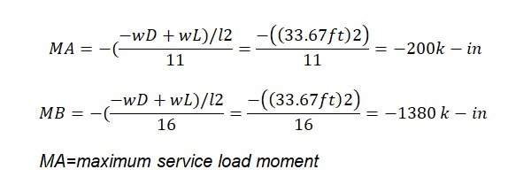
Another example of the considers a beam of with a simple span of 20 ft long and providing support for dead loads and a live load of 1 klf. The instantaneous (short-term) deflection is obtained by calculating D+L. Long-term calculations can also be calculated based on the application of dead loads which last for 3 years.
In this case:
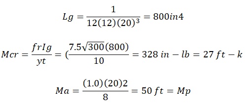
In this case, the parameters used in the above calculations include instantaneous and long-term dead loads and other values such as the curvature. In conclusion, creep, which has a negative effect on the long-term effect of concrete slabs, increasing the curvature of the slab, and causing an increase in stress and strain.
The conclusion from the study is that the short-term effect is not reliable in providing conclusive evidence on the sustainability of the composite slabs when used for construction purposes.
Comparison of Standards
New Zealand and Australia have similar composite material standards but are different from standards developed and adopted by the US and the European Union for composite slabs. However, the standards for the composite structures for the US and Australia have similarities. The difference between the Australian standards and the New Zealand standards is in the collaboration between New Zealand has the Euro code. Because of the wide range of composite materials and environments, the development of the standards is based on the requirements in the country of origin and the suitability of applying the standard in the designated country. The most appropriate composite material standard for Australia is the Australian standard for the construction of structures.
Analysis
Horizontal Shear Bond in Composite Slabs Investigations
It has been demonstrated by Veljkovic (1996a, p.34), Valipour and Bradford (2009, p.966), and Vinson and Sierakowski (2008, p.34), in research studies that the behavior of composite slabs is strongly influenced by the horizontal shear bond existing between the steel deck and the concrete used in the constructions of the composite material. According to the studies, different factors contribute to the different behavioral characteristics of composite slabs and include the thickness of the steel sheeting, the embossment used in the construction material, the length of the shear span, the shape of the steel deck profile, support friction, and the strain created in the steel sheeting. That is in addition to the thickness of concrete used and the arrangement of the load. That makes it difficult to create a single and consistent value that can be applied to each case of the composite slab (Vinson & Sierakowski 2008, p.34).
The full-scale design and tests discussed above are expensive to use to investigate the numerical values of the mechanical properties of composite slabs, making the finite element analysis a less expensive alternative (Zona & Ranzi 2011, p.34). In this alternative, the horizontal shear bond is modeled based on values yielded through elemental tests. In this study, the modeling is done based on the relationship between horizontal shear bond stress and the end slip. That is a radical departure from previous modeling which used connector or spring elements to yield data on the horizontal shear interaction. Research has shown that this model provides values that are similar to actual values obtained by conducting actual tests on the behavior of composite of composite slabs (Zona & Ranzi 2011, p.34).
According to Abdullah and Easterling (2007, p.34), different researchers have conducted experiments on the finite element analysis (FE) to study the effect of composite action on bonded slabs and develop numerical values that could be used in the design of bonded slabs for construction purposes. Zona and Ranzi (2011, p.34) discovered that the finite element method was suitable for only long-span slabs and when used for short-span tests, yielded values that showed poor relationship with the real values. Results by Zona and Ranzi (2011,p.34) led to new studies using shear bond end slip curves to analyze the effect of different composite slabs characterized by different slab slenderness, to determine the behavior of the composite slabs due to horizontal shear resistance. Here, Zona, Barbato, and Conte (2008, p. 123) analyzed the results and determined that slenderness is a ratio developed by relating the effect of the curvature and the shear span, and the effective depth. In the study, a relationship was established between slenderness parameters and the shear bond strength. When the value of the concrete thickness was increased, the shear bond strength increased, while an increase in the value of the shear span length decreased the value of the shear bond strength (Zona & Ranzi 2011, p.34; Standards Australia/Standards New Zealand 2002, p.39).
Under the finite element method, Zona and Ranzi (2011, p.34) showed that different shear bond end slip curve modifications could provide valuable data on the behavior of the composite slab under investigation. One of the approaches of making the modification on the curve was to introduce to the original shear bond end slip curve using a reduction function caused based on observed increase in the strain of the steel sheeting. In this experiment, the source of the reduction function was a result of numerous experimental studies that yielded a reliable value known as the reduction function, based on push and pull tests. The approach used in the experiment to determine the reduction function was to subject the steel sheeting to tensile strain and apply a force on the concrete, which made it to move over the steel sheeting. Benedetti and Mangoni (2007, p.221) shows that the action of the embossed interlock on the steel sheeting resulted in a reduction of the resistance between the elements, which when analyzed showed that a strong similarity with actual values obtained from experimental values on the behavior of real slabs.
Weaknesses with the finite element methods were because of the failure to use different or modified values in the experiment to study the characteristic of the shear bond end slip curve. An analysis of the values obtained from the finite element models showed the model to be suitable for studying the behaviors of long-span slabs. An analytical study of the composite action of the bondek slabs can be done using a finite element model based on the use of variable shear bond end slip curve model which model the behavior of the slabs at the interfaces. In the following discussion, the variations were made on the shear bond end slip curve in response to the different parameter of the slenderness effect. Bending tests were identified to be appropriate in the experiment instead of the push or pull out tests which could not accommodate the slenderness effect. The results could then be used to plot graphs of shear bond stresses against end slips. A PSC method was then be used to validate the values from the maximum and minimum stress values. Once the resulting values of the shear bond end slip curves were consigned to the connector elements of the finite element model, they were used as the basis for simulating the behavior of the action of the composite material consisting of concrete and the steel sheet. The level of accuracy of the resulting values was analyzed in the process (Benedetti & Mangoni 2007, p.221).
PSC Method
According to the EROCODE (2004, p. 2), the PSC method fails to provide appropriate methods for addressing the changes in the size of the composite slabs. In addition, the problem with the method is that the degree of interaction when determined from tests; the results obtained do not factor accurately concrete thickness and load positions. Typically, “slabs which are slender in size provide low ultimate moments and compact slabs yield high moment slabs” (Zona & Ranzi 2011, p. 25). Based on the conditions and the values yielded because of the variable degree of interaction between the composite materials, the variable shear bond can be calculated using the following formula (Benedetti & Mangoni 2007, p.221).

The number of variables and the corresponding results are plotted in the graph provided. Typically, the method can be improved to provide better results using the free body diagram approach discussed elsewhere in this paper.
Generating the Shear Bond Property
To study the effects of the composite action of the bondek slabs using the finite element model, it was critical to generate the shear bond property which was important in determining the action between the concrete and steel sheeting. One approach was to use the force equilibrium method to perform calculations to determine the value of the horizontal shear force and the slip relationships based on experimental data yielded from block bending tests (Benedetti & Mangoni 2007, p.221). A number of assumptions were made in deriving the Force Equilibrium method (Holomek, Karásek, Bajer & Barnat, 2012, p.345). The classical theory provided the basis for the following assumptions of the study.
- A uniform horizontal distribution of shear stress because the relative slip is uniform along the shear span.
- It is assumed that the displacement theory is valid
- The action of the plane and the natural axis are perpendicular
- Slip has a significant effect at the failing end and no the non-failing end.
- The steel deck shows elastic properties under the applied load up to the maximum load
- An assumption is made on the existence of stress on concrete in tension.
The shear bond force accommodates the frictional force at the support which contributes to the resistance that occurs at the interface of the elements in the investigation. Analytically, the axial force and the horizontal shear force are equal any time during the test period. It is also possible to for the steel deck to absorb the force due to the applied load by swinging about its axis. In this case, Ti depicts the axial force, Fi depicts the horizontal shear force, and Mri depicts the bending resistance which are caused by the steel deck. In this calculation, the self-weight of the concrete is neglected. With the assumptions taken, taking moments about the compression force, C enables one to calculate the value of the horizontal shear force Fi as follows, with the following variables used.
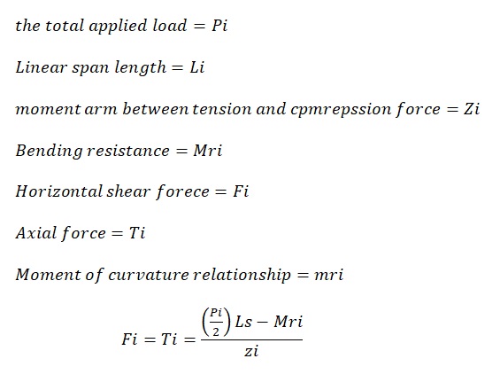
In this case, the Pi represents the total applied force, Ls represents the shear span length, and Zi represents the moment arm between the tension and compression forces.
The following expression was used to create a mathematical relationship between the curvatures to the moment arm.
The bending resistance is calculated based on the relationship between the curvature and the movement arm relationships. The bending resistance of the steel deck is calculated using the following equation.
In this case,
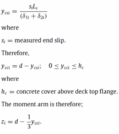
In the relation, therefore, the ycc reduces showing that the length of the crack of the composite neutral axis shifts upwards. Under similar conditions, ycs is seen to decrease. In this case, the length of the crack developed in the test can be determined as follows:
Calculating the Shear Bond Property Under Bending Tests
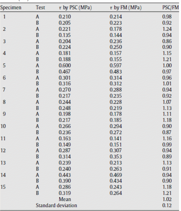
The test data collected from the experimental set up was subjected to the above equations, using equation one through to equation six to determine the horizontal shear bond force. The shear bond stresses were obtained dividing “the horizontal shear bond force values from the experiment by the values of the deck surface areas along the shear spans” (Zona & Ranzi 2011, p. 23). The values were “used to plot a graph against the values of the corresponding end slips’ (Zona & Ranzi 2011, p. 230. The relationship between the end slips and the shear bond slips could be obtained and validated from the experiment. It was important to validate the calculation method used in the experiment. To achieve that, the values obtained from the graph on the shear bond stresses were compared with the values obtained using the PSC method. A comparative analysis of the values showed little deviations between the actual and experimental values as tabulated below.
Contact Mechanism of Composite Slabs
In the process of investigating the composite action of bondek slabs, it is critical to investigate the contact mechanism of composite slabs. Research studies show that problems related to boundary conditions because of the nonlinear effect of composite slabs occur frequently and are influenced by the geometrical shape of the materials involved. As mentioned in the paper, it has been established that the mechanical bond, chemical, and the frictional bond provides the only basis for understanding shear transfer mechanism which is critical for establishing the type of force or bond existing between the concrete and the sheeting steel. In context, the chemical bond exiting between the concrete and steel determines the type of force or adherence established between the cement and the steel and the shear bond resistance. When enough opposing forces are applied on the concrete and the steel at the point of contact so that both materials act in the opposite direction with each other, and then bond between the two materials breaks, allowing slip to occur. In this case, the chemical bond does not act when slip occurs. The force acting perpendicular to the steel concrete interface leads to the creation of the frictional force that is normal and proportional to the normal force. On the other hand, the mechanical force is created by the physical interlocking between the materials used in the experiment.
When load critically is applied to the composite material, three types of environments occur in the order: adhesion, slippage, and disconnection respectively.
In this case, the adhesion property is experienced at the point of contact of the composite slabs. At this point, a uniform force, called the force of adhesion is experienced. When a positive relative movement occurs between the composite materials of the bondek slab, slippage is experienced in the tangential direction. However, of a displacement in an arbitrary direction occurs, there is a disconnection experienced with the composite slabs. Different researchers have developed different concepts on the composite action of bondek slabs. One such researcher is Coulomb who developed the Coulomb friction concept, which is used to mathematically the relationship between the tangential shear bond and the displacement that occurs at the steel and concrete interfaces. The mathematical relationship is shown below.
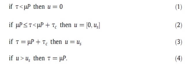
In the above equations, the tangential stress is represented by τ while Tc represents the prescribed cohesion which could be used to calculate the value of the sticking effect of the materials. The normal stress is P and the coefficient of friction, µ is taken to be constant in the above equations. A tangential displacement that occurs between the material si represented by u and us occurs when the displacement gradually becomes a slip.
Point Loading vs Normal Loads
A research study to determine the behavior of composite slabs when subjected to point loading and when subjected to normal loads to create the best method to design composite slabs was conducted using three point loading tests. In the tests, the design is to minimize the bond stress that is experienced using concrete slabs that have been decked in metal decking. In the study, it was determined to conduct a slip block test to provide appropriate data to develop a reliable composite slab design method. The aim of the study is to use the best method of evaluating the composite material’s interface shear strength. That is because most of the building materials are primarily subjected to static loads.
A summary of the test results show that composite materials subjected to excess point loading leads to interface bond failure, diagonal tension shear failure at the interface between the steel and concrete used to make the composite material. Research continues in the field of establishing the behavior of composite materials under normal and point loads to determine the action at the interface between the materials. It has been established that despite the method of loading varying between symmetrical and to central line loading, the shear bond failure has been identified in technical literature to be the common type of failure. One of the methods used in the study is the application of point loads which were applied repeatedly and static loads. In the test program, the specimen used included a single panel and nine two steel deck panels. The specimen had a span of 2150 mm between support centers. Materials used in the construction of test specimen included concrete, welded wire fabric, and cold-formed steel decking.
Test Procedure
The test was done to determine the ultimate load required for failure to occur, and the mode of failure of the composite material. In addition, the behavior of the composite material being tested was investigated in response to the applied loads at concentrated points. The maximum load that could lead to the failure of the composite material was determined using the following formula.
In this case, the weighted load factor, WL, when applied to the ultimate load provides the results for determining the ultimate failure load. By using live and dead loads, according to the specifications contained in CAN3-A23.3 standards, WL is calculated as follows.
According to research reports, it is important to apply a load ratio that is appropriate for defining the applied load cycle. The cyclic frequency of the applied load concentrated at specific points in the system was 3 Hertz in this experiment. The applied frequency was taken as applicable to avoid excessive vibrations during the test period.
Static Results
Erkmen and Bradford (2011, p.810) shows that the results on the deflection tests done using loads concentrated at specific points show horizontal slip to be the main cause that leads to the shear bond failure. Erkmen and Bradford (2010, p.2239) shows that the shear bond failure led to the loss in load carrying capacity of the composite material because of the occurrence of excessive vertical deflection. Vertical deflection was observed to occur at midspan with the end slip observed to occur when the ultimate load was reached. It is important to note that before the occurrence of shear bond failure, the steel deck had yielded to the applied load. In all cases when the tests were being conducted, the yielding did not extend to the top flanges (Fawzia & Fatima 2010, p.3).
Results from the investigations showed that end slip rose rapidly to the highest point and was sudden in occurrence. After the maximum value was achieved, further slippage did not occur (Fawzia & Fatima 2010, p.3). Different specimen used in the study showed different modes of failure because of the applied loads. The failure modes and the loads at which the failures occurred were because of the different behavioral characteristics of the bonds between the concrete slabs and steel. In addition, the crack patterns were also similar for each specimen used in the study. It was established that cracks developed showed the growth pattern taken when the forces were acting on the materials to cause cracking (Holomek, Karásek, Bajer & Barnat 2012, p.23). Other observations from the study showed that cracks were not caused by the application of large bending loads. Cracks observed to originate and spread from the central point load toward the point of support as spread with each progress in failure of the material under the load conditions (Fawzia & Fatima 2010, p.3). Typically, the following formula provides a method of calculating the elastic stress concentration factor.
The variables used in the above equation are detailed below.
Δ∂ – Elastic stress
ΔSn – Norminal stress
Deflections
It is important to note that the permanent defections were possible when the as the frequency of the applied load increased. As the frequency of the applied load increased, the rate of deflection was observed to correspond proportionally. Other materials showed relatively low deflection cycles with new changes in the applied load, leading to the conclusion that deflection achieved a constant value and with further applications of concentrated loads, no changes in deflection were observed until fatigue failure was observed. However, when fatigue was reached, defection increased sharply; and at some points occurred abruptly until permanent damage was caused. Different materials showed different defection characteristics. The conclusion is that the single span specimen used in the study showed a 55% ultimate static load failure when static loads were applied while the double span specimen registered a 60% failure of the static applied load. The results lead to the conclusion that continuity at the interior of the composite material
Materials Properties
Construction materials need to adhere to specific material properties to be suitable for the construction of buildings and other structures. Stress and Strain account for some of the properties that have to be investigated and determined for composite material used for the construction purposes.
Composite Construction and Design
It is important to provide an analysis of the construction and design of composite bondek slabs based on the knowledge that composite materials consist of more than one material combined together (Erkmen & Bradford 2010, p.34). A typical example is where concrete and steel make a composite material using different connectors to join the two materials together. In this study, reinforced concrete and steel are joined together to produce the composite material. The following diagram is a typical representation of the material.
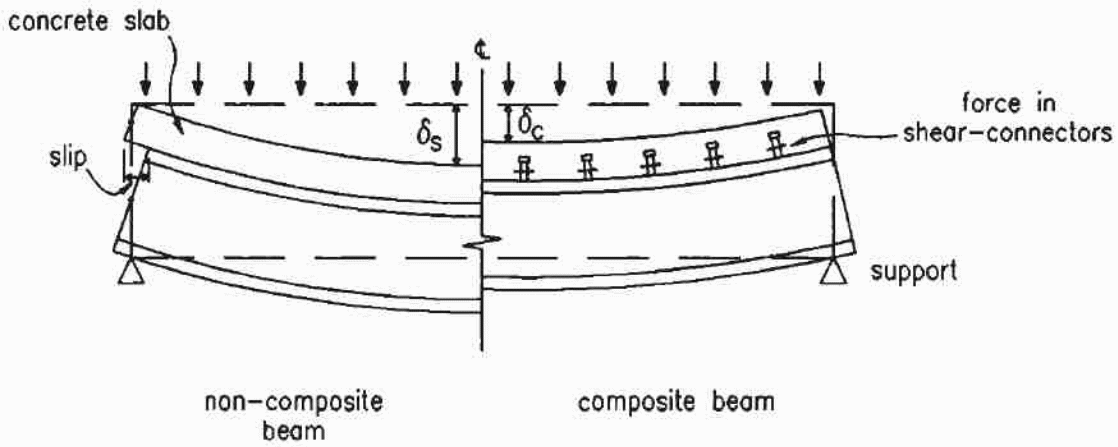
In the above case, a comparison is made between a composite material and a non-composite material and the forces acting on the material in both cases. According to the diagram, when vertical forces are applied on either of the materials, the non-composite material develops a significant deflection showing that it has lower resistance to the shearing force than the composite material. In the above diagram, the I-value is the one changed by the action of the forces, while the E-value remains constant. Typically, the result shows an increase in stiffness in the part of the non-composite material leading to a significant increase in the moment capacity which leads to a reduction in the size of the section of the material sunder investigations.
According to Erkmen and Bradford (2011, p.805), the deflections experienced with the above composite materials which consist of concrete and steel connected together shows that it is possible to resist the longitudinal shear forces acting on the composite slab. It is important to create an appropriate layout of the composite slab when designing and developing a composite structure. The diagram below shows how the layout plan of the composite materials is made (Erkmen & Bradford 2011, p.805).
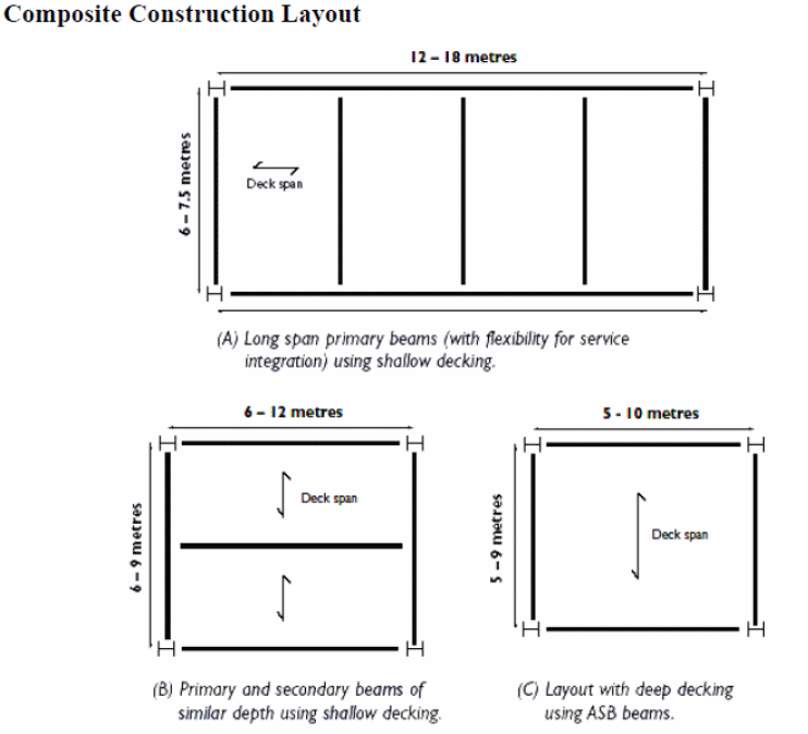
According to the Australian and American standards, the span is recommended to be 2.5 to 4.5m between the supports used in a structure. Calculations show that long spans of between 12 and 18 meters are possible if beams measuring 6 to 8 meters are used. In this case, the service integration is possible when considering the depth of the floor. The secondary and primary beams can be put to the best use by changing the spanning distances as shown below. In the following illustration, it is important to understand that continuous beams cause problems, but when used with care, provide good working results.
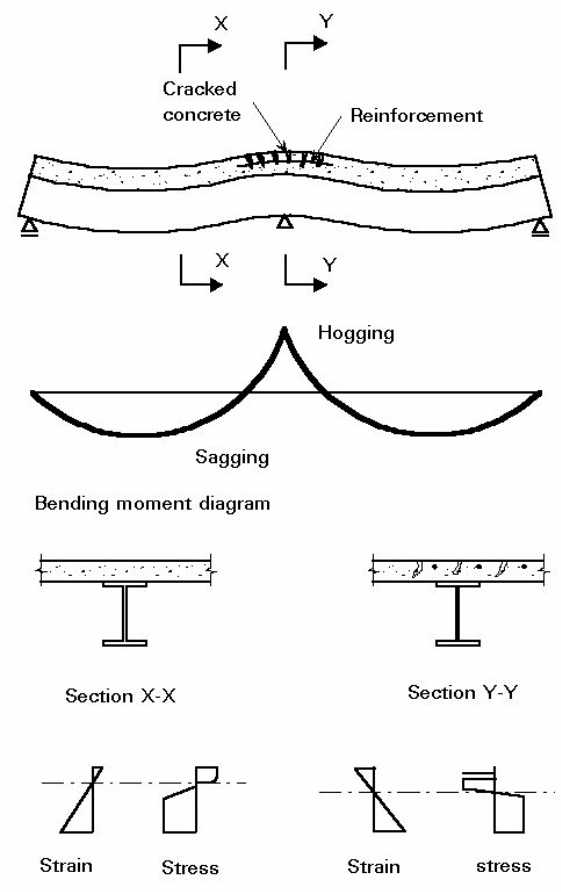
As shown above, the concrete cracks when subjected to forces acting over a support. In this case, it is important to ensure that the bending forces act only on the steel and not the concrete. According to Erkmen and Bradford (2011, p.805), the layout enables the composite material to be subjected to compression forces only.
To ensure system stability and to avoid buckling, it is important to provide additional support to overcome the effects of compression forces that act across the entire structure. In addition to that, the design should be made in such a way to avoid the effect of lateral torsional buckling (Erkmen & Bradford 2011, p.805).
Elements of Composite Construction
As illustrated in the flowing diagram, the elements used in the construction of the composite material are shown below.
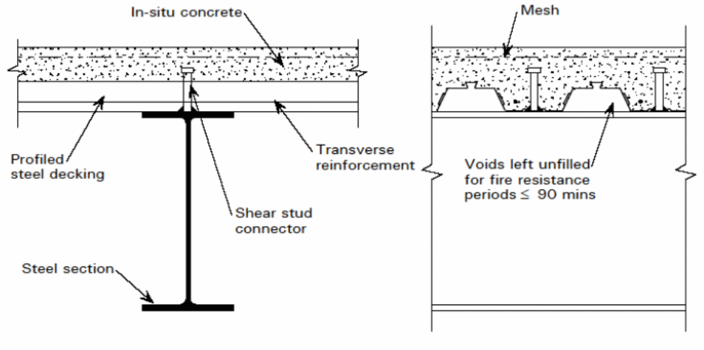
In that case, it is important to classify the decks and make appropriate designs with the right design parameters.
Moment Capacity
In this case, it is important to design the composite material such that the moment capacity exceeds the required capacity.
Pioneers who studied the moment capacity to understand the ultimate bending capacity was done by (Stark & Brekelmans 1990, p.34). In the study, the focus of investigations was on the contribution of normal forces to steel and the effect of reduced plastic on the steel deck, labeled as Mp. The results led to the formula shown below.
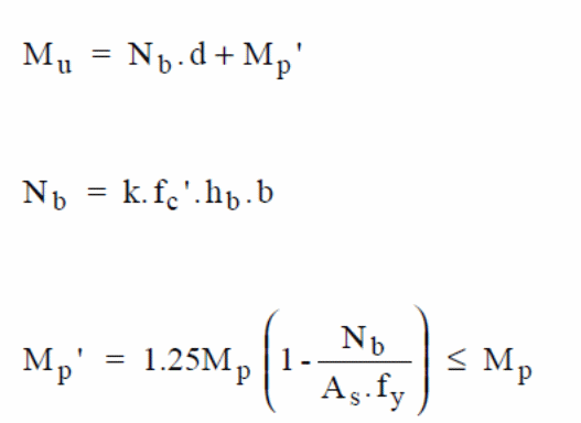
In the above formula, the ultimate bending moment is given by Mu with the steel deck plastic moment is given by Mp. In this case, the unit width of the slab is represented by the letter b and the steel deck yield stress is represented by. On the other hand, d represents repeat definition (Erkmen & Bradford 2011, p.805). The partial interaction theory, which is the basis of formulating the above expressions, is illustrated with the forces acting on the materials in the diagram below.

In the above diagram, the relationship between Mp and Nb are shown.
According to Erkmen and Bradford 92011, p.34).It is important to note that the nominal moment is Mn, with the number of studs used in the reinforcement to be represented by Nr and the Qn to represent the nominal shear study strength. The respective areas of the bottom steel flange and the web are provided by the symbols, Awebs, A bf respectively. It is possible to calculate the bending capacity of the composite slab using the following mathematical formula.
In the formula given above, the accumulated forces acting on the top flange is given by T1, T2, and T3. The Ti’s are e1, e2, e3, are variables for the moments of the arm under the force of compression exerted by concrete. It is also important to note that the shear bond length is provided by the following equation:
In the above case the shear bond length is given by Ls. on the other hand, the applied load on the concrete develops a normal force which is given by Ns. the variables use are described below.
t-shear strength
b-slab width
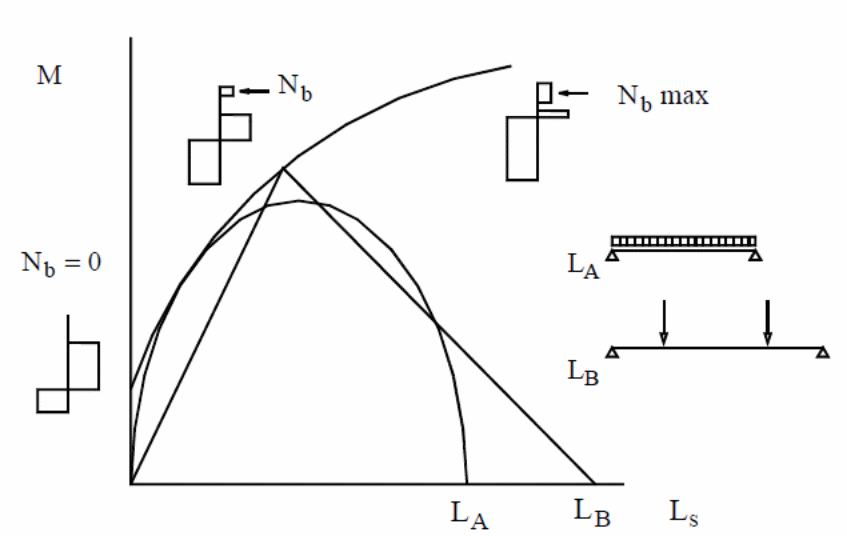
Using the interaction theory to analyze the interaction between the composite material and the action of the forces at the interfaces, the above curves were developed from the experimental results. The partial interaction theory, which uses the partial connection method, developed by the Patrick and Bridge (1990, 1994) provides the basis for studying the behavior of composite slabs. In this method, the key components factored include the anchorage method, the shear bond strength, and clamping forces the acting on the supporting sections of the composite concrete in a bondek material (Erkmen & Bradford 2011, p.34).
In the above case, the nominal bending moment defined by Mn can be calculated. A free force diagram can be used to determine the force, T, acing on the body of the steel deck, which is calculated using the following formula (Erkmen & Bradford 2011, p.34).
The variables used in the above equation are expanded and detailed in shear force diagram of figure 26 below.
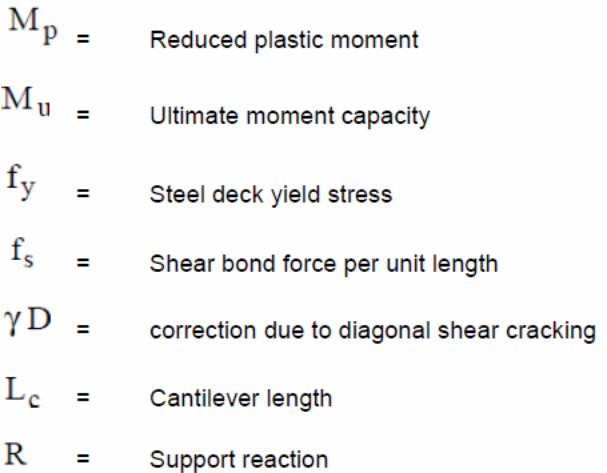
The force that resists the shear force acting on the concrete slabs is given by fs while the cantilever length is given by Lc, and yD is the shear cracking diagonal correction. The support reaction is given by R and the variable k is the fractional force due to the force, T.

Shear Capacity
When making the design, it is important to ensure that only the required or enough capacity is achieved according to the structural steel design standards.
Shear Connector Capacity
An adequate design that meets the Australian standards has to be met to achieve full composite capabilities. The extent of shear connection can be calculated using the following formula.
Nc—————-Compression force in concrete
Ncf ——– Compression force in the concrete with shear full connection
Longitudinal Shear Capacity
It is important to ensure that the design is able to absorb the action of the forces to avoid the concrete cracking (Spacone & El-Tawil 2004, p.150).
It is important to continuously check for the deflections, vibrations, and elastic behavior to ensure serviceability is achieved (Spacone & El-Tawil 2004, p.150; CSSBI1996, p.34).
A typical design diagram of composite beams is illustrated below.
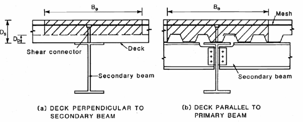
In the above case, the plastic theory is used to calculate the composite moment capacity. In this case, three situations are put into consideration as illustrated in the following diagram (Spacone & El-Tawil 2004, p.150). Different results are produced depending on the position of the plastic neutral axis shown in the following diagram.
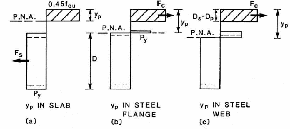
To determine the exact location of the PNA, it is important to create values for concrete and steel. In this case, let py be the stress for steel and 0.45fcu to be for concrete. The tensile capacity is calculated using the area, A of the beam. The expression for the tensile capacity is given below.
F = p
Measurements and calculations show the effective breadth to be equivalent to Be. It is important to determine the web and flange’s axial capacities using the following formula.
If the depth of the PNA is taken as yp, then, the three capabilities are prone to arise. The capabilities that arise are mathematically shown below.
- When PNA resides in the slap, then, Fc is found to be greater than Fs, and the following formula holds.

- In the second case, the steel flange accommodates PNA making Fs to be greater than Fc and the following mathematical formula can be used to calculate the Mc.

- In the third case, the steel web accommodates PNA and fw is greater than Fc, making the following formula appropriate to use in calculating Mc.

It is important to note that the moment of steel section is taken into consideration when making the numerical calculations using the formulas mentioned above. In that case, Ms = py Sx holds (Fawzia & Fatima 2010, p.5)
The following assumption about the effective breadth, Be holds.
The design is shown below.
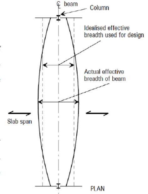
Accurate Numerical Values To Optimize the Composite Material
According to Fawzia and Fatima (2010, p.5), it is important to use accurate numerical values when designing composite slabs to optimize the composite material and get the best results in its usage in the construction of structures. That is because; the forces acting against the bonding between the steel and the concrete components can cause potential destruction to the structure (Fawzia & Fatima 2010, p.5). In this case, two situations are taken into consideration, perpendicular and horizontal decking as shown in the following diagram (Erkmen & Bradford 2010, p.34).
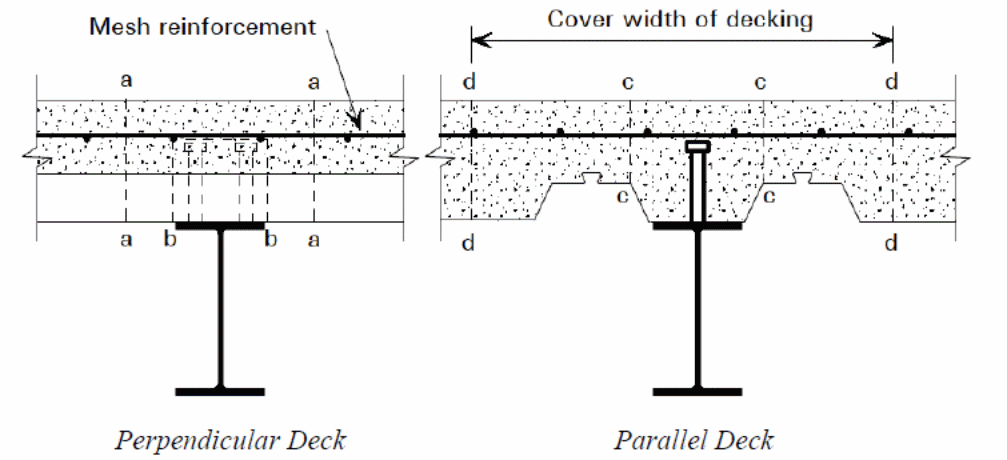
The critical failure planes are shown in the diagram to include a-a, b-b, and c-c. The force per unit length acting on the composite materials can be calculated using the following method.

The shear stud spacing is taken as s, while the number of studs used in this case is taken to be NT. When carefully designed, the resulting value is less than the capacity the slab is designed for. The relationship is found using the following formula.

The length of the failure that occurs is Ls and the Asw is the reinforcement per unit area.
Computational Model
Rapid advances in the application of computers to investigate composite action of bondek slabs have different computer models developed. One such research is on a computer model that has a continuous slab with different structural responses to different forces. In this case, a finite element method was conducted using the Atena software to perform shear defection tests. A 3D model was used in this case, because the 2D model had limitations. The critical elements include thermal and static analysis. In this case, different thermal parameters were applied after which, normal temperature analysis was conducted. The temperature leading, according to the model, to thermal failure and reduced shear strength was noted. An analysis of the shear bearing capacity were tabulated and graphed below.
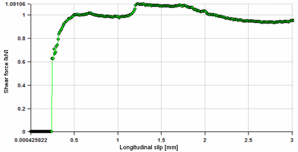
Findings based on the above model show that computerized modeling provides adequate details of the parametric values for thermal and mechanical forces that cause deflection of the composite material. The models provide accurate values of the shear and strain forces that act at the boundary of the composite materials.
Distribution of Shear Force in Concrete Slabs
It is important to study the distribution of forces on composite concrete slabs using analytical means.
Cracking of FRP Slabs
Research conducted to determine the conditions under which cracking of composite concrete slabs occur is critical in determining the design of concrete structure (Erkmen & Bradford 2010, p.34). In the study, it was established that concrete slabs reinforced with FRP behaved differently from concrete structures reinforced with steel. The difference in the behavior of the materials was caused by the differences in binding characteristics between concrete and the bonding materials. In that context, FRP has lower modulus of elasticity compared with steel reinforcements.
According to the observations made from the study, Erkme and Bradford (2010, p.2239) shows that the mechanical characteristics of the FRP and other steel reinforced concrete influence the behavior of the materials when subject to different loads. In this case, because FRP has a low modulus of elasticity, cracking of the concrete slab occurs abruptly when subjected to deforming loads (Erkmen & Bradford 2010, p.34). That is in addition to the fact that larger cracks occur on the FRP reinforced concrete for the same length of material subjected to similar load conditions. In addition to that, the de-bonding that occurs at the outer coating of the rebar causes the slippage that of the GFRP. A study of the cracking load leads to the discovery of the effects of the forces that influence the cracking of the composite material (Erkmen & Bradford 2010, p.34).
Cracking Loads (Pc)
In this case, the above formula was used to calculate the approximate value of the cracking moments using the modulus that is calculated from the transformed section of the material under investigations. According to the above formula, the modulus of rapture is fr with the section under tension and the centroidal axis having a distance of Itr. Erkme and Bradford (2010,p.2239) conducted an experimental study to compare the results obtained from the tests and the actual results using the above formula and real data. The results showed a 65% difference between experimental and real results. According to Erkme and Bradford (2010, p.2239) the transformed modulus is higher than the effective modulus, based on experimental and actual values. It has been established that the concrete has an effective depth that lies between t and t-c (Erkme and Bradford 2010, p.2239).

According to Erkmen and Attard (2011, p.234), if the thickness of the slab is reduced, the results differ slightly with the original values. In this case, M’ is the value of the cracking moment and the reduced moment of inertia is Ir. A comparative analysis of the results shows the above method to have a higher degree of reliability compared with other methods. The values obtained have insignificant differences with actual experimental values (Erkmen & Attard 2011, p.234).
Deflection of FRP slabs
Erkmen and Bradford ( 2011, p. 805) have shown that different models and codes which have been developed by different bodies provide values that can be used to compare deflection effect caused because of the application of different forces based on models (Erkmen & Attard 2011, p.234). Two type of models have been used in this case include the prediction deflection model and the AC Canadian building models. The ACI Building Code proved a guideline on the values obtained from an immediate deflection of composite member that has been cracked using the empirical equation shown below (Erkmen & Attard 2011, p.234).

The effective moment of inertia is given by Ie and the optimum value of the applied force that causes deflection is given by Ma. In the above equation, the moment of inertia is given by Ig. Based on actual and experimental values obtained from the above equations, the results show FRP values of deflection to be significantly overestimated (Erkmen & Attard 2011, p.234).
The CEB-FIP Code (990) was another model developed for the purpose of calculating deflection caused on composite slabs because of the forces of deflection that acted on composite slabs. According to the model, the applied moment and the rigidity of the composite concrete slabs are used to calculate the curvature of the material under investigations (Erkmen & Attard 2011, p.234). In this equation,
Φi is the curvature, M is the moment, the elastic modulus, and I is the rigidity of the section.
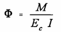
Iu (2008, p.2934) shows that the variables used in the above equation include the elastic modulus of the concrete that is used in the experiment, Ec, and the moment of inertia, I of the span. A geometric relationship between the variables that used in determining the curvature and other variables in the equation are illustrated in the following formula, which is used to calculate the amount of deflection in the simply supported slab (Iu 2008, p.2913).
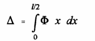
Kroflič, Saje and Planinc 2011 p.34) and Iu (2008, p.23) show that by measuring the distance, x, from the left end of the supported slabs, and the span to be l, the above equation can be integrated for any section of the span as shown below.
An analysis of the above equation shows that the distances of the curvature and the incremental values added to the variables provides more accurate results. It is important to note that the curvature at the non-cracked section is lower than the curvature at the cracked section of the composite material (Kroflič, Saje & Planinc 2011 p.34). In the calculation of the curvature, it is important to assume the concrete tension. The curvature of the non-cracked section is calculated using the following formula (Kroflič, Saje & Planinc 2011 p.34).
It is important to note that the degree of stiffness increases with the presence of spacing within the cracks, making a decrease in the amount of deflection caused. If an empirical interpolation factor is introduced into the mathematical relationship, then, based on the CEB-FIP code, the mean curvature can be calculated using the following formula (Kroflič, Saje & Planinc 2011 p.34).

In that case, the empirical factor interpolation factor can be calculated using the following formula according to the conditions shown besides the formula.

In this case, the variables are related with each other as shown below.
The bond condition is defined by the β1 value. In this case, the β1 value is sustainably kept at 0.5 for different load cycles (Kroflič, Saje & Planinc 2011 p.34). The results show that the value of the cracking loads for the reinforced FRP concrete slabs are lower than the values of the concrete reinforced with steel (Kroflič, Saje & Planinc 2011 p.34).
The Yield Line Theory of Composite Slabs
Kroflič, Saje and Planinc (2011, p.34) argues that the basis for determining the amount of load to be applied on composite slabs and ensure that the load can be safely sustained when the composite material is used in construction engineering is the yield line theory. According to Kroflič, Saje and Planinc (2011, p.34), in this theory, the applied loads and the effect of the loads are investigated. The surface forces that act on the composite material at the point of contact with the loads shown below.
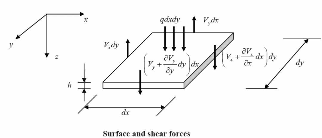
Typically, the moment forces and the membrane forces are shown in the diagram below.
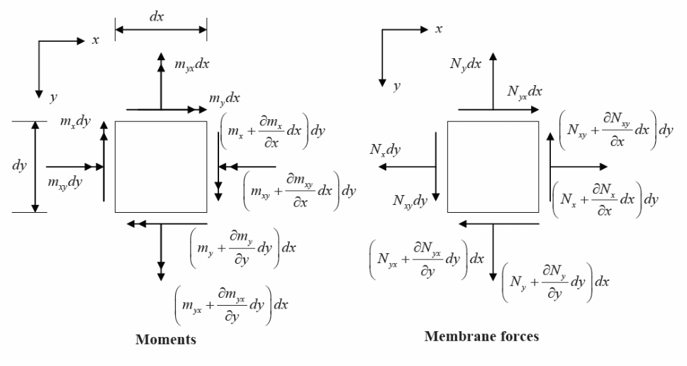
According o Liew, Chen and Shanmugam (2001, p.234), the analytical method used in this case is based on the elastic theory. In this case, the theory is based on Lagrange’s deductions and equations which are based on isotropic plates with loads acting normally to the plane of action. A mathematical expression for solving the arising problem is shown below.

It is important to note that the variables used in the equation are summarized below.

Here, Liew, Chen and Shanmugam (2001, p.234) detailed a study on the research conducted by Navier in 2003 on the formula developed by Lagrange to discovered determine Fourier’s series, and developed another equation that accurately addressed the problems associated with the formula developed by Lagrange. The new formula is shown below.
In the formula, a number of variables were used to determine the values that could be applied in a practical situation. The variables are described below.
Panel side length = a, b
Integer values = m, n
Boundary conditions constants = C, Amn
Liew, Chen and Shanmugam (2001, p.234) established a number of findings were determined from the use of the above analytical methods. According to the yield line theory, it is possible to make predictions on the appropriate load that a slab can sustain and the forces that the slab can resist before failing. It was also established that the ductility of the composite materials allowed for the formation of the slab (Erkmen & Saleh 2012, p.23).
Finite Element Analysis (FE)
Studies by Ayoub (2001,p.23) and a parallel research by Benedetti and Mangoni (2007, p.233) established that the finite element method provides accurate methods of calculating the loading deflections based on the curves used in developing different methods used to test the FE method. Different methods were used in this case to model the behavior of composite slabs under different load conditions to determine the effect of the applied load on the degree of deflections produced by the composite material. According to the Erkmen, R & Saleh (2012, p.23) shows that in the application of the Finite Element analysis it is important to change the shear bond property of the composite slabs under investigation and the actual material used in the construction industry. The slenderness of the slab under consideration in this case, and the actual material used in the construction industry should have the shear bond property altered to ensure accurate modeling of the finite element analysis is done correctly.
According to Tzaros, Mistakidis and Perdikaris (2010, p.1234), it is important to use the single property curve to determine accurate values for the right geometry of the composite curve in question. In this case, the push off tests have been identified as ideal in providing accurate results which, however, cannot be applied in other situations that use different geometries (Ayoub 2001, p.929). The following diagrams show the nature of the finite element method based on the typical shear bond response behavior and the response provided when using a different materials with varying slenderness (Ayoub 2001, p.929).

Implementation
Investigations into different methods of understanding composite action of bondek slabs, widely drawing on different material; characteristics and behaviour shows the best methods of implementing the design. Typically, it is important to design for temperature, shear stress, shear strain, vertical and horizontal loading in relation to the composite action of the slabs. Different design, development, and installation manuals have been developed based on results from obtained from the studies. One of the requirements for installation of the composite is based on the maximum deflection requirements and the behaviour of the composite slabs under different conditions. It is important to note that the support lines under the general design principles based on the rules developed by BHP research institute according to the British Standard BS 5950: Part 4: 1982. Material specifications, deflection limits, loading parameters, slab geometry, corrosion protection, and fire resistance are specified under the ANSI/ASCE 3-91, Australian Standard, AS5100.6, and several other standards. That is in addition to the AS36000-2009, AS3600-1994 and AS3600-2001 standards for composite slabs.
Industrial and Experimental Results
Industrial and experimental results on the composite action of composite slabs based on different tests shows different outcomes. Small scale tests show shear bond failure with significant slips, with the critical sections showing significant cracks. Major vertical separation occurs on slabs with fewer straps compared with slabs having straps positioned along similar lines. Typically, the factors affecting slab strength are similar for both industrial and experimental results. The causes include maximum load and deflections, end slips, mid-span defections of 0.02 in. Industrial and experimental values on the effect of slab thickness show that shear capacity of the composite slab increases with increase in thickness. On the other hand, experimental details show that end details have a significant influence on the behavior of composite slabs. Results show that end slenderness behavior on the application of load which cause deflection shows that the capacity of the composite slab to defection loads increases exponentially with decrease in slenderness. On the other hand, the finite element method is suitable for conducting comparative studies between real and experimental data to make accurate results on the best data to use under different conditions.
Conclusion
The motivation of experimental studies into the behaviour of composite bondek slabs when subjected to different shear stress and shear strain leads to the discovery of the behaviour of composite materials at the action of the forces. In this study, investigations show that experimental data varies to a significant extent with real data on the behavior of composite slabs. It has been demonstrated that failure can only occur when the shear stress and shear strain acting on the materials exceeds the bonding action between steel and concrete. Temperature influences the membrane action of the composite material, with the finite element method shown to provide unrealizable data in design making when designing the composite material. It has been demonstrated that numerical modeling, computer modeling, and other analytical methods need to be conducted and the data compared with Australian building code standards to make decisions on designing composite materials. There is need for further studies to determine the best methods that could provide reliable data for the design of composite materials. New integral models need to be created to optimize research. There is need for further research on the differences between the Australian standards and other standards under different environments to determine the most suitable standards for compliance purposes.
References
Abdullah, R & Easterling, W S 2003, Structural Evaluation of a new composite deck profile: Phase II. Rep. No. CEE/VPI-ST03/01, VPI&SU, Blacksburg, VA.
Abdullah, R 2004, Experimental Evaluation and Analytical Modeling of Shear Bond in Composite Slab, Ph.D. dissertation, VPI&SU, Blacksburg, VA.
Abdullah, R & Easterling, W S 2007, ‘Determination of Composite Slab Strength Using a New Elemental Test Method’, Journal of Structural Engineering, vol. 9, no. 113, pp.1268-1277.
Abdullah, R & Easterling, W S 2008, “A New Method for Modeling the Horizontal Shear Bond in Composite Slabs”, The Journal of Constructional Steel Research, vol.1, no.1, pp.234.
Abdullah, R & Samuel Easterling, W 2009, “New evaluation and modeling procedure for horizontal shear bond in composite slabs.” Journal of Constructional Steel Research, vol. 65, no. 4, pp. 891-899.
Abdullah, R & Easterling, W S 2007, ‘A new small scale testing method for composite slabs’, Journal of Structural Engineering, ASCE, vol. 9, no. 133, pp. 1268-1277.
An, L 1993, “Load Bearing Capacity and Behaviour of Composite Slabs with Profiled Steel Sheet,” Ph.D. Dissertation, Chalmers University of Technology, Sweden.
American Society for Testing and Materials (ASTM) 1991, “Standard Test Method for Comparing Concretes on the Basis of the Bond Developed with Reinforcing Steel”, ASTM C 234-91, vol. 4, no. 02, pp. 234
Australian Steel Institute (ASI) 2009, Design Capacity Tables, Volume 1, Fourth edition 2009.
ASCE 1992, Standard for the Structural Design of Composite Slabs. ANSI/AASCE 3-91, American Society of Civil Engineers, New York.
ASTM C31/C31M-00e1 2002, Standard Practice for Making and Curing Concrete Test Specimens in the Field, West Conshohocken, PA
ASTM C39/39M-01 2002, Standard Test Method for Compressive Strength of Cylindrical Concrete Specimens, West Conshohocken, PA
Ayoub, A. 2012, “Analysis of composite frame structures with mixed elements – state of the art.” Structural Engineering and Mechanics, 41(2), 157-181
Ayoub, A & Filippou, F 2000, “Mixed Formulation of Nonlinear Steel-Concrete Composite Beam Element.” Journal of Structural Engineering, vol. 126, no. 3, pp.371-381.
Ayoub, A. 2005, “A force-based model for composite steel-concrete beams with partial interaction.” Journal of Constructional Steel Research, vol. 61, no. 3, pp.387-414.
Ayoub, A. 2001, “A two-field mixed variational principle for partially connected composite beams.” Finite Elements in Analysis and Design, vol. 37, no.11, pp. 929-959.
Benedetti, A & Mangoni, E 2007, “Analytical prediction of composite beams response in fire situations.” Journal of Constructional Steel Research, vol. 63, no. 2, pp.221-228.
Bode, H & Dauwel, T 1999, “Steel-Concrete Composite Slabs – Design Based on Partial Connection.” Proceedings of the International Conference on Steel and Composite Structures, vol. 2, no. 1-2, pp.10.
British Standards Institution 2002, Testing hardened concrete – Part 3: Compressive Strength of Test Specimens. BSI, 12390-3:2002.
Bode, H, Minas, F & Sauerborn, I 1996, “Partial Connection Design of Composite Slabs.” Structural Engineering International, vol. 1, no. 1, pp. 53-56.
Bode, H & Sauerborn, I 1992, “Modern Design Concept for Composite Slabs with Ductile Behavior,” Proceedings of an Engineering Foundation Conference on Composite Construction in Steel and Concrete II, vol. 1, no.2, pp. 125-141.
Bridge, R Q & Patrick, M 1996, “Research on Composite Structures in Australia 1960-1985,” Proceedings of the Engineering Foundation Conference on Composite Construction in Steel and Concrete III, ASCE, pp. 41-54.
Bursi, O, Sun, F & Postal, S 2005, “Non-linear analysis of steel–concrete composite frames with full and partial shear connection subjected to seismic loads.” Journal of Constructional Steel Research, vol. 61, no. 1, pp.67-92.
Cas, B, Bratina, S, Saje, M & Planinc, I 2004, “Non-linear analysis of composite steel-concrete beams with incomplete interaction.” Steel and Composite Structures, vol. 4, no. 6, pp.489-507.
Chen, S, Shi, X & Qiu, Z 2011, “Shear bond failure in composite slabs – a detailed experimental study.” Steel & Composite structures, vol. 11, no. 3, pp. 233-250.
Chen, S & Shi, X 2011, “Shear bond mechanism of composite slabs — A universal FE approach.” Journal of Constructional Steel Research, vo. 67, no. 10, pp.1475-1484.
CSSBI. 1996, Standard for Composite Steel Deck, CSSBI 12M – 96, Canadian Sheet Steel Building Institute.
Dall’Asta A. & Zona, A. 2004, “Comparison and validation of displacement and mixed elements for the non-linear analysis of continuous composite beams.” Computers & Structures, vol. 82, no. 23-26, pp. 2117-2130.
Dall’Asta, A. & Zona, A. 2004, “Three-field mixed formulation for the non-linear analysis of composite beams with deformable shear connection.” Finite Elements in Analysis and Design, vol. 40, no. 4, pp. 425-448.
Dall’Asta, A. & Zona, A. 2002, “Non-linear analysis of composite beams by a displacement approach.” Computers & Structures, vol. 80, no. 27-30, pp. 2217-2228.
Daniels, B J & Crisinel, M 1993a, “Composite Slab Behavior and Strength Analysis. Part I: Calculation Procedure.” Journal of Structural Engineering, vol. 119, no. 1-4, pp.16-35.
Daniels, B J & Crisinel, M 1993b, “Composite Slab Behavior and Strength Analysis. Part II: Comparisons With Test Results And Parametric Analysis.” Journal of Structural Engineering, vo. 119, no. 1-4, pp. 36-49.
Erkmen, R & Bradford, M 2010, “Elimination of slip-locking in composite beam-column analysis by using the element-free Galerkin method.” Computational Mechanics, vol. 46, no. 6, pp. 911-924.
Erkmen, R & Saleh, A. 2012, “Eccentricity effects in the finite element modeling of composite beams.” Advances in Engineering Software, vol. 52, no. 2, pp. 55-59.
Erkmen, R & Attard, M 2011, “Displacement-based finite element formulations for material-nonlinear analysis of composite beams and treatment of locking behavior.” Finite Elements in Analysis and Design, vol. 47, no. 12, pp. 1293-1305.
Erkmen, R & Bradford, M 2011, “Treatment of slip locking for displacement-based finite element analysis of composite beam-columns.” International Journal for Numerical Methods in Engineering, vol. 85, no. 7, pp.805-826.
Erkmen, R & Bradford, M 2010, “Locking-free finite element formulation for steel-concrete composite members.” IOP Conference Series: Materials Science and Engineering, vol. 10, no.1, pp. 2239.
Fawzia, S & Fatima T 2010, Deflection Control in Composite Building by Using Belt Truss and Outriggers Systems. World Academy of Science, Engineering and Technology, vol. 1, no.4, pp. 1-6.
Eurocode 4 1994, Design of Composite Steel and Concrete Structures, Part 1.1, General Rules and Rules for Buildings. ENV 1994-1-1:1992, European Committee for Standardization, Brussels.
Fragiacomo, M., Amadio, C & Macorini, L 2004, “Finite-Element Model for Collapse and Long-Term Analysis of Steel-Concrete Composite Beams.” Journal of Structural Engineering, vol. 130, no. 3, pp. 489-497.
Holomek, J, Karásek, R, Bajer, M & Barnat, J 2012, Comparison of Methods of Testing Composite Slabs. World Academy of Science, Engineering, and Technology vol. 67, no.1, pp. 1-6.
Huang, Z, Burgess, I W & Plank, R J, 2004, “3D Modelling of Beam-Columns with General Cross-Sections in Fire”, Paper S6-5, Third International Workshop on Structures in Fire, Ottawa, Canada, vol. 1, no.1, pp. 323-334.
Johnson, R P 1994, Composite Structures of Steel and Concrete, Beams, Slabs, Columns, and Frames for Building. Blackwell Scientific Publication, Oxford.
Kroflič, A, Saje, M & Planinc, I 2011, “Non-linear analysis of two-layer beams with interlayer slip and uplift.” Computers & Structures, vol. 1, no.1, pp.34.
Liew, J, Chen, H & Shanmugam, N 2001, “Inelastic Analysis of Steel Frames with Composite Beams.” Journal of Structural Engineering, vol. 127, no. 2, pp.194-202.
Lim, L, Buchanan, A., Moss, P & Franssen, J M 2004, “Numerical Modelling of Two-Way Reinforced Concrete Slabs in Fire”, Engineering Structures, vol. 26, no. 1, pp. 1091.
Iu, C 2008, “Inelastic finite element analysis of composite beams on the basis of the plastic hinge approach.” Engineering Structures, vol. 30, no. 10, pp. 2912-2922.
Nie, J, Cai, C & Wang, T 2005, “Stiffness and capacity of steel–concrete composite beams with profiled sheeting.” Engineering Structures, vol. 27, no. 7, 1, pp. 74-1085.
Nie, J, Cai, C, Zhou, T & Li, Y 2007, “Experimental and Analytical Study of Prestressed Steel-Concrete Composite Beams Considering Slip Effect.” Journal of Structural Engineering, vol. 133, no. 4, pp.530-540.
Patrick, M & Poh, K W 1990, “Controlled Test for Composite Slab Design Parameters.” IABSE Symposium, Brussels, Belgium – Mixed Structures, Including New Materials, Zurich, Switzerland.
Patrick, M & Bridge, R Q 1994, “Partial Shear Connection Design of Composite Slabs.” Engineering Structures, vol. 16, no. 5, pp.348-362.
Patrick, M 2004, Composite Beam Shear Connection Design and Detailing Practices for Australian Steel Decks, Western Sydney.
Ranzi, G, Al-Deen, S, Ambrogi, & Uy, B 2013, Long-term behavior of simply-supported post-tensioned composite slabs, Journal of Constructional Steel Research vol. 88, no. 2013, pp. 172–180.
Sakr, M & Sakla, S 2008, “Long-term deflection of cracked composite beams with nonlinear partial shear interaction: I — Finite element modeling.” Journal of Constructional Steel Research, vol. 64, no. 12, pp. 1446-1455.
Sakr, M & Sakla, S 2009, “Long-term deflection of cracked composite beams with nonlinear partial shear interaction — A study using neural networks.” Engineering Structures, vol. 31, no. 12, pp. 2988-2997.
Salari, M & Spacone, E 2001, “Analysis of Steel-Concrete Composite Frames with Bond-Slip.” Journal of Structural Engineering, vol. 127, no. 11, pp.1243-1250.
Salari, M. and Spacone, E 2001, “Finite element formulations of one-dimensional elements with bond-slip.” Engineering Structures, vol. 23, no. 7, pp. 815-826.
Schuster, R M 1973, Composite Steel-Deck Reinforced Concrete Systems Failing in Shear-Bond. 9th Congress – International Association for Bridge and Structural Engineering, Amsterdam, Holland.
Schuster, R M 1970, “Strength and Behavior of Cold-Rolled Steel-Deck-Reinforced Concrete Floor Slabs,” PhD Dissertation, Iowa State University, Ames, Iowa.
Siu, W & Su, R 2011, “Analysis of side-plated reinforced concrete beams with partial interaction.” Computers & Concrete, vol. 8, no. 1, pp.71-96.
Smitha, M & Kumar, S 2013, “Steel–concrete composite flange plate connections — finite element modeling and parametric studies.” Journal of Constructional Steel Research, vol. 82, no.1, pp.164-17.
Spacone, E & El-Tawil, S 2004, “Nonlinear Analysis of Steel-Concrete Composite Structures: State of the Art.” Journal of Structural Engineering, vol. 130, no. 2, pp.159-168.
Standards Australia/Standards New Zealand 2002, Structural design actions, Part 0: General principles, Appendix C, Guidelines for Serviceability Limit State (Informative), AS/NZS 1170.0.
Tzaros, K. Mistakidis, E & Perdikaris, P 2010, “A numerical model based on nonconvex–nonsmooth optimization for the simulation of bending tests on composite slabs with profiled steel sheeting.” Engineering Structures, vol. 32, no. 3, pp. 843-853.
Valipour, H & Bradford, M 2009, “A steel-concrete composite beam element with material nonlinearities and partial shear interaction.” Finite Elements in Analysis and Design, vol. 45, no. 12, pp. 966-972.
Veljkovic, M 995, “Longitudinal Shear Capacity of Composite Slabs.” Nordic Steel Construction Conference ’95, Malmo, Sweden.
Veljkovic, M 1996a, “Behaviour and Resistance of Composite Slabs,” Ph.D. Thesis, Lulea University of Technology, Lulea, Sweden.
Vinson, J R &. Sierakowski, R L 2008, The Behavior of Structures Composed of Composite Materials, 5 editionth, Web.
Widjaja, B R & Easterling, W S 1996, “Strength and Stiffness Calculation Procedures for Composite Slabs.” Proceedings of the 13th International Specialty Conference on Cold-Formed Steel Structures, St. Louis Missouri, pp.389-401.
Zona, A & Ranzi, G 2011, “Finite element models for nonlinear analysis of steel–concrete composite beams with partial interaction in combined bending and shear.” Finite Elements in Analysis and Design, vol. 47, pp. 2, pp. 98-118.
Zona, A, Barbato, M & Conte, J 2008, “Nonlinear Seismic Response Analysis of Steel-Concrete Composite Frames.” Journal of Structural Engineering, vol. 134, no. 6, pp. 986-997.