Diagram Analysis
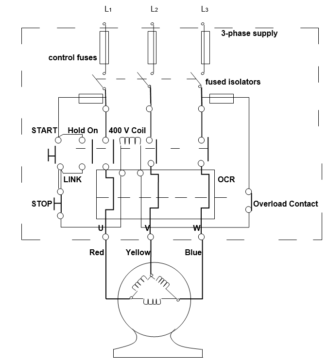
The above is the diagram of the Direct On-Line (DOC) starter connected to the 3-phase cage rotor induction motor. Control fuses at the top of the diagram are necessary for the process of voltage control and the starter performance monitoring (Payne, 2007, p. 110). Fused isolators are used for providing access to the rotor in case if a failure occurs and the rotor is to be switched off, disconnected, and maintained. The power and the control circuits are the two obligatory starter elements (Payne, 2007, p. 111). The power circuit is presented in thick lines, while the control circuit is in thin lines. The 400 V Coil is supplied to the diagram to provide an equal voltage of 400 V per supply line (Payne, 2007, p. 111). Start and Stop buttons serve the purpose of switching the starter on and off in case of necessity.
The link between the Stop button and the Start button is designed from the three wires. Two of those wires from the mutual connection between the buttons, while the third wire serves the purpose of connecting the Stop button with the Hold On contact. The latter is designed for putting the starter in the waiting regime while the voltage is supplied to the supply lines of the starter but the starter as such and the motor are switched off by pushing the Stop button (Payne, 2007, p. 111).
The overload contact allows the maintenance of the starter in a proper regime and with the necessary voltage rates. The indicator of the overload contact informs the starter user about the mechanism overload and is the first sign that over- or under-voltage protective means will soon be implemented (Payne, 2007, p. 114). Over Current Relay, also known as OCR, is used for protecting the motor from overload. Finally, the red, yellow, and blue wires serve the purpose of connecting the DOL starter to the 3-phase cage rotor induction motor.
Protection and Safety Concerns
The operation of any piece of electric equipment is associated with the danger of fire, explosion, or any other unexpected and undesirable results. To protect the plan or any other facility where the equipment is operated from the above dangers, the electric circuits, both power and control circuits, are provided with the Over Current Relay and fuse protection devices (Payne, 2007, p. 132).
Over Current Relay
The Over Current Relay is the device that is designed for prevention and signaling the overcurrent in the starter. The procedure of the Over Current Relay operation includes three major stages. Depending on the number of phases included in the starter operation process, Over Current Relays can be one-, two-, or three-phase ones. Accordingly, the first stage in the process of Over Current Relay’s operation is the measurement of the current in every phase provided in the starter (Payne, 2007, p. 129).
As soon as the Over Current Relay identifies the increased, or decreased, current in a phase, it first starts sending the alarm signal to the overload, or underload, contact on the starter. This is the second stage in the protective work of the Relay. The final, third, stage in its work is the process of circuit-breaker tripping and the re-closure of the whole circuit (Payne, 2007, p. 131).
Fuse Protection
The mechanism of fuse protection devices’ operation is similar in its aim as fuses also protect the electric device from increased or decreased electricity supplies, current issues, and overloads (Payne, 2007, p. 133). The actual process of fuse operation is based on the concept of fuse rating and the inability of the protected device to operate at higher current rates than fuse ratings allow.
Accordingly, the control fuses, as shown in the above diagram, are simply turned off as soon as the current in any phase, or in all phases in total, exceeds the maximum allowed fuse rating (Payne, 2007, p. 133). Therefore, fuse protection is required for the operation of any power and/or control circuit and for the proper and safe work of a DOL starter. The Over Current Relay is a required element in the circuit as well due to the same reasons, i.e., the need to provide safety in handling the electric equipment.
Full Load Current: Fuse Rating and Over Current Relay Setting
The concept of the full load current, fuse rating, and the Over Current Relay setting are integrally connected and equally important for circuit protection. Thus, the full load current is the maximum allowed current at which a device, a DOL starter in our case, can operate without damages to its parts and overall performance (Payne, 2007, p. 135). The fuse rating is the maximum allowed current under which the fuses installed in the device, i. e. the DOL starter, can operate without melting or exploding. The fuse rating is directly related to the full load current, as the latter cannot be higher than the fuse rating, while the fuse rating should conform to the full load current levels (Payne, 2007, p. 137).
The relation of the Over Current Relay setting to both full load current and fuse rating is somewhat different. Over Current Relay, a setting can be high and low depending on the need to protect the starter from either over- or under-current (Payne, 2007, p. 137). Accordingly, the high setting of the Over Current Relay should conform to the full load current and fuse rating levels, while the low setting is the marker of the minimum allowed current for the DOL starter operation.
Single-Phasing
The so-called process of single phasing is one of the most widely spread causes of motors and starters’ failure alongside overloads and contamination. The essence of single phasing is in the fact that while a motor is operated by the three-phase current lines, one of the phases might be lost due to either the lack of current supply or the overcurrent and fuse blowing in this phase (Payne, 2007, p. 143).
Accordingly, for the three-phase circuits, sing-phasing is a considerable problem because if one phase is lost, the circuits cannot provide the fitting current load to the starter and the motor fails to operate properly (Payne, 2007, p. 144). For solving the issue of single phasing, the Over Current Relay can be of help as it signals the coming overload of the phase, or its undervoltage, and further facilitates the circuit reclosing if the problem with the current is not eliminated.
Star / Delta starter
The operation and maintenance of the Star / Delta starter are more complicated and costly. Moreover, the work of Star / Delta starter is associated with the higher voltages and involves outside current’s occurrence that might increase the load on the motor. Finally, switching between the power and control circuits of the Star starter and Delta starter, as well as between the Star and Delta starters as such involves additional energizing of the circuit (Payne, 2007, p. 171).
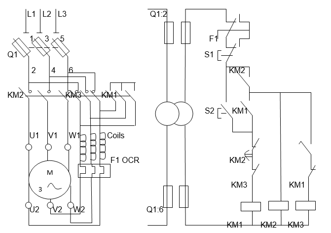
Star / Delta starter consists of current phases, fuses, wires, contactors, and the Over Current Relay. As well, the starter operates with the help of Start and Stop buttons, fuse isolators, and motor coils. Fuse isolators are used for closing the fuse controls and preventing the current from open streaming while the motor is operated. The operation of the Star starter begins with the manual closure of the fuse isolator. The next step is the closure of the contractors, one of which connects the motor to the Star starter (KM2), the second one provides current supply for the motor (KM1), and the third connects the motor to the Delta starter (KM3) (Payne, 2007, p. 173).
The current phases, there are three of them in the starter, provide current to the motor, while fuses control the over- under-load of the current phases and prevent the motor failure. The function of the Over Current Relay is to monitor loads of the motor and signal any cases of deviation from the allowed norm. Finally, motor coils connect the Over Current Relay with the contactors, thus providing the access to current measurement (Payne, 2007, pp. 174 – 175):

Fault Finding
The major precaution related to the fault-finding procedure is to avoid generalizations and be systemic in the search for the faults (Payne, 2007, p. 196). As well, before looking for faults, it is necessary to conventionally divide the circuit into smaller systemic units and identify the function of each of those units. Finally, an examination of the circuit for missing components, broken details, or blown fuses should be carried out (Payne, 2007, p. 196).
Four most often observed motor faults that can be identified during the fault finding procedure include the situations when line contactors make and break continuously, stops of the motor after it started following the Start button push, stops of the motor after Star starter accelerations, and blowing of fuses in the progress of change for Delta starter (Payne, 2007, p. 196). The likely cause of the line contactors’ fault is an insufficient wired connection, whose weakness does not allow the contactors to function properly.
The weak connection of the Start button with the current coil might be the cause of the motor stopping after the Start button is released. Stops of the motor while transiting from one starter to another one are likely to be explained by weak contactors that do not allow transmitting enough current to energize the motor. Finally, blowing fuses in the process of Delta starter change can be explained by the fault of the coils as fuses blow under the conditions when current exceeds the fuses rating level.
Works Cited
Payne, John C. The Marine Electrical and Electronics Bible. Sheridan House, 2007. Print.