- Overcurrent relay and fuse protection necessity
- Relate the fuse rating and overcurrent relay setting to the full load current
- Describe how thermal overcurrent relay protects this condition.
- Summary of the operation of the starter
- Procedure and precaution to adopt before any faulty finding
- The likely cause of the following
- Work cited

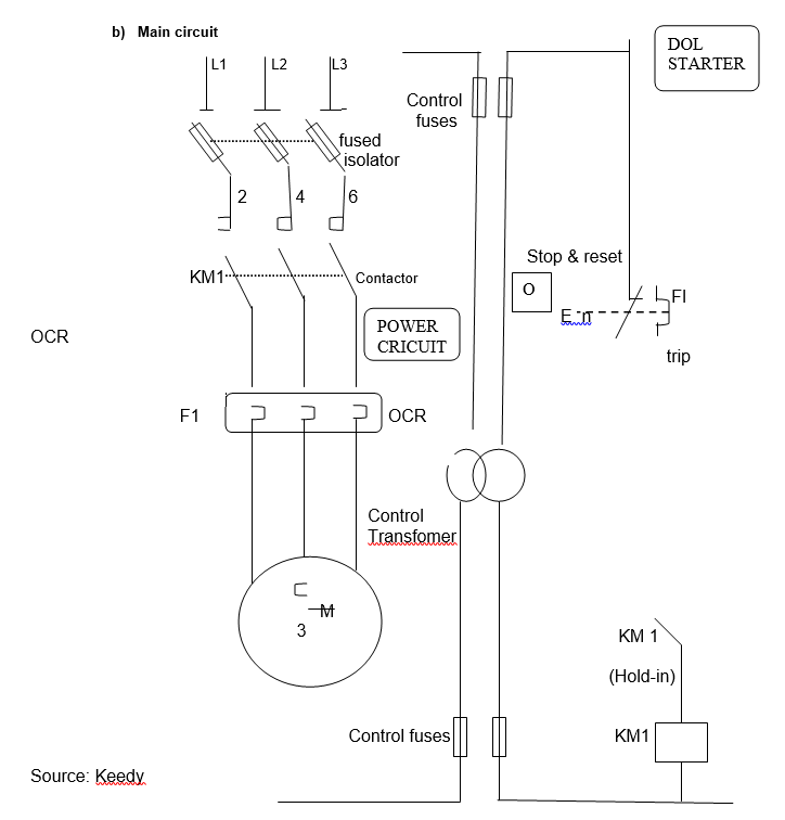
- Control circuit: This is available in the control transformer and is 110 Volt.
- Start: The start button is used for local and remote auxiliary contact cause the contactor to be energised which close KMI main and auxiliary contact.
- Stop: Stopping motor normally involves pressing local or remote push button to de-energise the main contractor and coil KMI.
- Fuse: The purpose of the fuse is to protect the short circuit as well as provide protection for the coil, and this will energise the voltage at a normal of 70%.
Overcurrent relay and fuse protection necessity
The protection of current and fuse is essential to clear a fault. The device is also to enhance the backup method. Thus, protection is very essential to detect overcurrent in the equipment, and this will lead to instantaneous clearing of the fault that might have arisen. It should be noted that the protection of the current relay and fuse is desirable to minimise the damage that might arise from the fault. In addition, the protection is used to prevent or minimise hazards that might have arisen when the system is unstable and there is a complete loss of power from the system. (Qua-Tech Engineer, Inc).
The protection of overcurrent relay and fuse protection is required because the overcurrent relay and fuses are used to distribute the power system. Typically, the relay is an electromechanical device that contains many features and is used for elements that are associated with ground fault protection and there is a need for backup protection to achieve suitable settings. The protection is also needed against a ground-fault current that might arise from a lower current and this might produce faulty magnitude. Protection is also needed against overcurrent from Phase C to Phase A, and greater security is essential to protect the phase from phase-ground fault. Thus, there is a need for protection against the crossover of the fuse. (Essex Energy).
Relate the fuse rating and overcurrent relay setting to the full load current
The purpose of overcurrent is to provide acceptable compromise on over current protection. Thus, the relay coordinates the maximum amount of fault current that can interrupt the circuit breaker. The fuse coordinates the total clearing time for a fuse to preload. In addition, the fuse serves the purpose of protecting the contactor from short-circuit. (Qua-Tech Engineer, Inc 4).
Thus, the relationship between fuse rating and overcurrent relay setting to the full load current is that the relationship is to protect the device from the faulty current. (S&C Electric 3).

The single phasing denotes the distribution of current electrical power where all voltages are supplied in unison. Typically, the single-phase is applicable in heating and loading large electrical motors. The standard frequencies associated with a single phase are 50 or 60 Hz. A load of a single phase is powered from the distribution of 3 phases, and the application of single-phase is seen to use for low voltage where the network is very low.
The single-phase has a very simple AC circuit and this is called a power circuit. From the wiring, the source of power is the AC source. (Kuphaldt 20).
Describe how thermal overcurrent relay protects this condition.
The thermal overcurrent relay provides overcurrent protection devices that are associated with starting motor contactors. The method that the thermal overload relay provides protection is that it detects overcurrent in the motor and converts the current to heat in a resistive element. Typically, the simplicity of thermal overcurrent relay makes it to be very effective in protecting overcurrent where it can respond to changes and ambient temperature. (US Army Corp of Engineers 3)
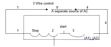
The diagram show motor coils between the labelled terminals

Summary of the operation of the starter
The starter operation should be to press the start button to energise and close KMI. The operation can be done locally or remotely. Moreover, by closing KMI, the pushbutton will be released. Typically, the fuse will also protect the circuit and coil. This will make the motor stop normally.
The operation of the starter is to lower the voltage to protect the motor from overloading. Typically, the operation of the starter is used for the motor to run which makes the motor move very fast.

The over-current relay is located in the Phase at the run.
Procedure and precaution to adopt before any faulty finding
There is a need to make a safe disconnection from supply to achieve maintenance purposes. The additional procedure and precaution are to check the following:
- To test motor overhead
- To check short circuit
- To check under voltage
- Check overcurrent relay
- Check whether the Fuse in the supply line
- Ensure that Contactor drop at approximately 70% voltage
The likely cause of the following
Supply is available, but the motor does not start
The reason that leads the motor not starting as a result of induction where its starting current is several times more than the running current of the which not back by emf. Typically, the induction of starting current may have 3 phases where the motor is 6 times higher than its running current. Thus, voltage drops because the cable connects to the motor with its source. Meanwhile, when the voltage drops below 80%, the motor will not start.
The higher capacity of the motor that is connected to the system may lead to the voltage being dropped which will lead the system to stop due to heavy voltage drop. Essentially, the result of full voltage in the configuration with the starting of the motor may result in the rush of the current to the motor and this may damage the winding and may also lead to the burning of the motor, and this may lead to the situation where the motor does not start. (Yahoo 1).
Line Contactor makes and breaks continuously
A contactor is being controlled from the application of a throttle footswitch. Typically, the contractor is an electromagnetically switch that carries a large amount of current. The proper operation of the contactor consists of coil voltage, availability of continuous current, and availability of break current and durability of the contact surface. The major factor that may make the contactor break continuously is when there is a lack of continuous current that passes through the contactor.
Additionally, the breaking of the contactor may be a result of the disconnection of the current. Typically, the coil in the contactor should be strong enough to keep the motor moving and should be able to break the flow of current. Thus, with coil voltage should be between 20 volts and 48 volts. Thus, in the situation where there is too much voltage, this will burn the coil wiring and this will lead to the contactor developing fault and lead to its breakage. (Csuk 3).
Motor stops when the start button is released
The cause is that the voltage regulator is faulty. It should be noted that when the motor starts under normal conditions, the motor will run when the button is released. However, when the motor stops when the starts button is released, the other reason is that there is overloading in the opening and this result may break the path to the coil. The result is the motor will not automatically restart because the memory contact has already opened. Typically, overload can also make the current of the motor pass through the heater coil that may lead to the breaking of the coil, and this will cause the motor to stop when the start button is released. (Shultz 4).
O.C.R trip when the motor reaches full load
One of the major causes of motor failure is overload. Typically, 30% of the failure in motor results from overload. It should be noted that there can be a trip of O.C.R when the motor reaches full load if 10 a 10Hp motor cannot produce and this can lead to the increase in the motor temperature.
It should be noted with the result of over-current when the motor reaches overloading, this will cause the heat being built in the motor and this will result to tripping of O.C.R, and the outcome will be the failure of insulation in the motor, and this also leads to increase in the temperature of the motor by 10-degree centigrade. There is the occurrence of overcurrent when the current that carries the normal load is higher than the normal current. Thus, the major factor that leads to this is overloading. With overload, a short circuit will greatly exceed the normal current of the circuit, and this will lead to the circuit leaving the normal current that is carrying the current. Thus, the motor may be tipped with this type of current. (Bussmann 2).
Motor accelerates in the start then stop
The cause of this problem is that both delta and starter require connection were connecting to star lead to the reduction of voltage by about 60%. Thus, when the motor is switched to delta, and if the voltage is not ideal there may be 65% load torque, and this is too small and this may make the motor stop when accelerating in star. The excess torque can cause damage to the system. It should be noted that in the star delta, the driven instar is approximately 80%, and when the load is above 80%, the motor may accelerate in star and stop. (Soft Star Direct).
The blocking of the motor which is the cause of mechanical seizure may make the motor stop suddenly. Typically, the sudden increase in electrical load may make the controller hot, and this may generate a large amount of electrical noise, and this may lead the motor to Motor accelerate then stop.
Fuse blow when starter change from start to delta
The typical cause of fuse to blow when starter change from start to delta is that the delta has a different current from the starter. Thus, changing the start to delta can lead the circuit to be overheated which can cause the fuse to blow. It should be noted that inrush of current associated with motor starter can cause interaction problems to fuse and inrush current can cause dynamic overvoltage, which may cause the fuse to blow.
Typically, the switch to start to delta will make the transient current reach a high peak and this has been found to exceed the normal operation of DOL. (Harrison, 1).
Work cited
Bussmann, Cooper. “Motor Protection Voltage Unbalance and Single-Phasing”., Progress Energy. 2003. Web.
Kuphaldt, Tony.R.Lessons In Electric Circuits, Volume II – AC,. 6th ed.USA. All about Circuit.2007.
Csuk, Richard. Technical Note 010: Lessons Learned, Why are Fuses and Solenoid Disconnects So Important in EV’s, Alltrax, 2007. Web.
Essex Energy. Electronic Overcurrent Protection, Essex Energy Corporation, 2009. Web.
Harrison, Richard, L. Predictive/Preventive Maintenance, Who needs it, Inframation, 2002. Web.
Qua-Tech Engineer Inc. OVERCURRENT COORDINATION GUIDELINES FOR INDUSTRIAL POWER SYSTEMS, The Electrical Power Engineer, 2003.
S&C Electric. Overcurrent Protection of Transformers — Traditional and New Fusing Philosophies for Small and Large Transformers, S&C Electric Company, 2003.
Shultz, George P. “Transformers and Motors”, Price Minister, 1991.
Soft Star Direct, Why Soft Starts?. Web.
Keedy, D.J. Assignment 0832, 0842, 0843 Starters, Protection, Fault Finding, South Tyneside College.
US Army Corp of Engineers. CHAPTER 4 SECONDARY ELECTRICAL DISTRIBUTION, US Army Corp of Engineers Publication, 2006. Web.
Yahoo. What is the reason behind using a star-delta and DOL starter for A.C motors? Yahoo Answers, 2009. Web.