It is important to note that a comprehensive analysis and design of modern systems require the knowledge and skills to utilize various visual techniques of database relationships. There is a wide range of options available, such as a data flow diagram (DFD) or entity relationship diagram (ERD). The given assessment will primarily focus on ERD use for the Fab Flowers case, which corresponds to the second option of the assignment. Therefore, ERD flowcharts enable a greater illustrative ability to showcase relational databases in regard to debugging and designing systems.
ERD Component Analysis
The current environment of system development is constantly and continuously changing. In order to enhance the systems development life cycles, it is vital to be equipped with methods of demonstrating the relationships within a system visually (Valacich & George, 2020). ERD can be defined as “a type of flowchart that illustrates how ‘entities’ such as people, objects or concepts relate to each other within a system” (Lucidchart, 2022, para. 1). In other words, it has applicability in a number of areas where system development is needed, such as research, education, information systems, business, or software engineering. Business analysts encourage the use of ERDs or DFDs since “a picture is worth a thousand words – somebody surely captured a lot in this saying” (Sharma, 2015, para. 1). Therefore, ERD is a powerful tool for communicating and expressing the underlying intricacies of a system.
It should be noted that key components of ERD include attributes, relationships, and entities. Attributes are usually depicted with oval circles, and they can have cardinality, single value, multi-value, attribute categories, and description (Lucidchart, 2022). Relationships are shown with diamonds, and some relationships can be recursive, where “the same entity participates more than once in the relationship” (Lucidchart, 2022, para. 19). When it comes to entities, these are definable data storing units illustrated as rectangles. They can be described in terms of keys, categories, sets, and types (Lucidchart, 2022). For instance, products, cars, students, customers, or people are entities. The given three essential components comprise the entity relationship diagram.
Entity Relationship Diagram
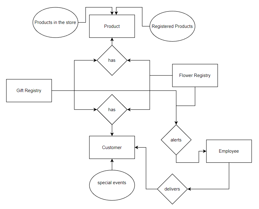
The entity relationship diagram is shown below in Figure 1. The case provides information on key entities, relationships, and attributes denoted with a rectangle, diamond, and oval, respectively. There are two registries, which are entities containing information on gifts and flowers. They have data on products and customers, and the former’s attributes are the in-store products and registered ones. The latter is an entity with an attribute of special events, and when they occur, an employee is alerted to prepare and make arrangements to deliver the identified product to the customer. However, the key limitation of the ERD is to “understand that the purpose is to show relationships. ER diagrams show only that relational structure” (Lucidchart, 2022, para. 38). Thus, it might require complementing the framework with more substantive data on the properties of each element.

Conclusion
In conclusion, system development requires a wide range of methods of depicting and communicating its key elements. ERD is a powerful and effective visualization tool to ensure that a system is demonstrated comprehensively. Its applications can be found in areas that include research, education, information systems, business, or software engineering. One should be aware that attributes, relationships, and entities are core aspects of a completed entity relationship diagram.
References
Lucidchart. (2022). What is an entity relationship diagram (ERD)? Web.
Sharma, A. (2015). Data flow diagrams—Are they worth it?BA Times. Web.
Valacich, J., & George, J. (2020). Modern systems analysis and design (9th ed.). Pearson.