Problem Statement
The problem has three statements, and they are (a) how to find an aircraft altitude using the information gathered on the magnetic field of the aircraft (b) how to translate the magnetic field of the aircraft from the aircraft coordinate system to the earth (c) how to find the attitude of the aircraft.
Background
The earth’s magnetic field is a complex three-dimensional force that varies in intensity and time and as per different locations. The variations are due to differences in the earth’s mantle, crust, magma, iron ore deposits, and other structures and also due to the effect of the sun. The US Geological Survey has been monitoring the variations in the magnetic field since 1843 by setting up different observatories and survey centers (1). A very accurate map of the actual geomagnetic force with respect to the longitude and latitude has been created. This map is called the geomagnetic chart, and a typical chart is shown in Figure 1. Geomagnetic Map.

The chart tells us precisely the magnetic force at a particular coordinate defined by the latitude and the longitude.
- How to find an aircraft altitude using the information gathered on the magnetic field of the aircraft.
NGDC (National Geophysical Data Center provides an online calculator that allows the magnetic field values to be computed based on latitude, longitude, elevation, and time. The results provide the required magnetic field values at any point in time. It is possible to develop software in a handheld device or a computer carried on board the aircraft and calculated the magnetic field value. If this is not possible, then the Geomagnetic Chart of the Earth tells the magnetic forces prevalent at a particular latitude and longitude.
- How to translate the magnetic field of the aircraft from the aircraft coordinate system to the earth’s
Caruso has explained that the attitude parameters of an aircraft can be defined as per three angles, and they are the pitch, heading, and roll. These angles are always with reference to the local horizontal plane, which is the plane normal to the gravitational vector of earth. The heading is the angle in the local horizontal plane measured clockwise from the true north earth’s polar axis direction. Pitch is the angle between the longitudinal axis of the aircraft and the local horizontal plane, and Roll is the angle about the longitudinal axis between the local horizontal plane and the actual flight orientation. The three angles are illustrated in Figure 2. Coordinate direction (X,Y,Z) and attitude orientation (roll, pitch) on an aircraft.

At any given point of time, if an aircraft was positioned on the local horizontal plane, then the roll and pitch angles are zero, and the heading angle would be: arcTan(Yh/Xh). Xh and Yh are the earth’s horizontal magnetic field components.

In the above figure, roll and pitch tilt angles are referenced to the right and forward directions. The X, Y, and Z magnetic readings can be transformed to the horizontal plane by applying the following rotation equations:
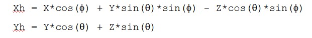
A hand held device or a laptop computer can be used to calculate the heading angles using the log tables. Formulas for calculating the heading angles are (4):
Heading for (Xh <0) = 180 – arcTan(Yh/Xh) for (Xh >0, Yh <0) = – arcTan(Yh/Xh) for (Xh >0, Yh >0) = 360 – arcTan(Yh/Xh)
for (Xh =0, Yh <0) = 90 for (Xh =0, Yh >0) = 270
- How to find the attitude of the aircraft.
The previous two questions have given answers to finding the magnetic forces on the aircraft and How to translate the magnetic field of the aircraft from the aircraft coordinate system to the earth. The last question to be answered is how to find the attitude of the aircraft.
Caruso has suggested a compass system that would provide a to provide an output heading for a given orientation. The minimum requirement for the compass is a three-axis magnetic sensor that has a two-axis tilt. A schematic illustration is shown in Figure 4 Compass System Block Diagram.

The main components of the system are a Tilt Sensor, a 3 Axis magnetic sensor, an ADC, and a processor with an algorithm for converting the inputs to provide a heading. It must be noted that the attitude accuracy of the system is affected by errors such as Analog to Digital converter resolution, Magnetic sensor errors, Temperature effects, nearby ferrous materials, Compass tilt errors, and Variation of the earth’s magnetic field.
ADC Resolution errors can be achieved by using a magnetic sensor with angular resolutions of 0.1 degrees and which has a low hysteresis of less than 0.08 and a high amount of linearity. Temperature effects can be canceled by using appropriate digital and analog circuits. Magnetic Sensor errors can be compensated by using solid-state magnetoresistive sensors with a resolution of fewer than 0.07 gauss can be used to cancel the errors of the magnetic sensors. Errors due to nearby ferrous materials can be compensated by eliminating all hard and soft ferrous material near the compass and by demagnetizing the zones near the aircraft. Compass tilt errors can take care of by proper installation of the compass since this error provides a wrong reference plane and must be eliminated. Variation in the earth’s magnetic field can be corrected by using the Declination Chart.
References
- USGS, National Geomagnetism Program: Program Summary, [Online] 2007. Web.
- Declination Chart, The International Geomagnetic Reference Field 200, [Online] 2001.
- NGDC, Estimated Values of Magnetic Field Properties,[Online] 2004.
- Caruso Michael J. Applications of Magnetic Sensors for Low Cost Compass Systems, Scientific Honeyweller, vol. 8, no.1, 1987.
- Rohac Jan, Accelerometers and an aircraft attitude evaluation, Dept. of Measurement, Faculty of Electrical Engineering Czech Technical University in Prague, Document ID 0-7803-9056-3/05, IEEE, 2005.