Abstract
Aircraft have been part of our lives for a very long time. Although we might not be dealing with aircraft on a daily basis, most of us, at some point in our life, will use an aircraft to travel from one destination to another. The purpose of this report is to explore aircraft instrumentation and system. This report gives us an insight into some of the basic flight instruments in an aircraft, also known as the “six-pack” and their operating principles. The report further goes on to discuss navigation systems such as the Instrument Landing System (ILS).
Introduction
Aircraft have various navigation instruments depending on their categories. These instruments range from the fundamental instruments to highly developed and complex systems of contemporary airlines and fighter jets (Department of Aerospace Engineering, 2004, p. 2). The last decades have seen an increase in the number of aircraft instruments and systems.
The initial experimental aircraft had no instruments. As a matter of fact, a magnetic compass was one of the first instruments to be introduced. When air travel became more than mere experimentation, a few engine indicators were introduced. They were followed by the altimeter, speed indicators, and, soon after, aircraft systems meant to help the pilots during the long journey were introduced (Department of Aerospace Engineering, 2004, p. 3).
Many airline passengers often wonder how the aircraft flies and what it uses to determine the altitude and direction. This forms the basis of this report. The report will explore the instrumentation used in aircraft and flight instruments. Many basic flight instruments will be discussed, for instance, the airspeed indicator and magnetic compass.
In addition, some vital concepts, for example, the pitot-static system and the vacuum gyro system, will also be explored. The report will also cover more complex systems such as the instrument landing system and the auto-pilot system, among others. Through these discussions, hopefully, we will be able to understand the significance of the instruments and systems in the aircraft and the entire aviation industry.
Flight Instruments
Nearly all the aircraft instruments are assembled in the cabin panels. They are visible and plausibly set. Differentiating aircraft instruments from avionic systems is somehow not easy because most of them are usually linked to one another. Based on the conventional definitions, the most common flight instruments include magnetic compass, altimeter, airspeed indicator, vertical speed indicator, gyroscopes (altitude gyro, turn rate gyro, directional gyro), and turn coordinator (Federal Aviation Administration, n.d., p. 1).
These instruments provide crucial information to the crew members, which include aircraft’s speed and altitude. The crew members must be able to understand and identify any fault linked to these instruments. Generally, instruments are used when there is poor visibility, mainly attributed to bad weather (Department of Aerospace Engineering, 2004, p. 3). The basic aircraft instruments constitute what is generally referred to as the six-pack instruments.
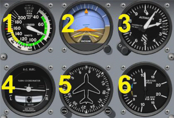
These are airspeed indicator, attitude indicator, altimeter, turn coordinator, gyroscope, and vertical speed indicator (Federal Aviation Administration, n.d., p. 1). Figure 1 illustrates a characteristic “six-pack” as they appear in the cockpit. The instruments are numbered as follows:
- Air Speed Indicator,
- Altitude Indicator,
- Altimeter,
- Turn Coordinator,
- Directional Gyro,
- Vertical Speed Indicator.
Magnetic Compass
A magnetic compass is among the earliest aircraft instruments. Given the fact that the earth produces a considerable magnetic field, this instrument can be used to establish flight direction. The compass indicates the aircraft’s direction with respect to the earth’s magnetic field (Federal Aviation Administration, n.d., p. 2). However, the magnetic compass also has a number of weaknesses.
The first weakness is because of the orientation of the magnetic influx lines closer to the magnetic poles, that is, at high latitudes. As a matter of fact, these regions tend to be more parallel to the surface of the earth since they conjoin towards the poles. For that reason, compass needles are indecipherable at high latitudes. This inaccuracy is often known as the “dip error” and can be corrected by changing the needle above its center of gravity (Federal Aviation Administration, n.d., p. 3).
The above correction can also result in another error, that is, the error of inertia forces, which always force the needle to move backward and forwards. Nonetheless, this error can also be compensated by immersing the equipment in a liquid. The liquid used is normally a mixture of oil and alcohol. Another error that is common with a magnetic compass is declination error.
This error is attributed to incongruence between the magnetic axis and the earth’s geological axis. The magnetic flux lines are often upset by the subversive mineral components. This error can be corrected by understanding the flight area’s declination. This is always provided on the flight maps and manuals (Federal Aviation Administration, n.d., p. 3).
Last but not least, the variation in the needle can also be caused by other aircraft components. This includes metallic components and electrical systems. Such deviations are always monitored while the aircraft is still on the ground and can be corrected by introducing a compensating magnet. The compensating magnet reports any form of deviation. The current aircraft systems are based on magnetic compass and gyroscopes (Federal Aviation Administration, n.d., p. 3).
The Altimeter
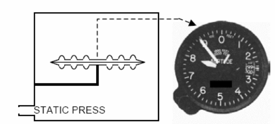
This is an instrument used to gauge the aircraft’s altitude based on the atmospheric pressure and temperature. This is because the barometric measurements are derived from atmospheric pressure. The pressure measurements are compared to the predetermined value of pressure and temperature. The temperature of a stable air has been tentatively found to decline as the altitude increases at a rate of 6.5 degrees Celsius per kilometer (Department of Aerospace Engineering, 2004, p. 4).
The altimeter measurements are very significant since they indicate how high the aircraft is above the ground, mountain tops, tall buildings, and telecommunication towers, among other objects (Department of Aerospace Engineering, 2004, p. 4). High altitude has also been associated with Hypoxia. Hypoxia is defined as a deficiency of oxygen in the body tissues or simply oxygen starvation. The precaution and cure for hypoxia in the aerial environment can be achieved in two fundamental ways: providing enough oxygen and by flying an aircraft at a relatively low altitude.
Unluckily, it is normally not possible to accomplish both. Aircraft pilots are always required to fly at secure altitudes because of weather and terrain. For this reason, the medical escort is supposed to exchange a few words with pilots before and during flights regarding the impact of elevation. They should advise the pilot on the best altitude to fly the plane based on the altimeter readings (Ghosh & Pant, 2010, p. 8).
In small aircraft, an altimeter is only used to measure atmospheric pressure. This is because the pressure changes with altitude. However, air pressure and temperature may be affected by weather changes. This is why the altimeter reading is always compared with the predetermined values, which indicate the actual height above the sea level. Therefore, an altimeter is a very important instrument in the aircraft (Edexcel Limited, 2009, p. 2; Federal Aviation Administration, n.d., p. 7).
Air Speed Indicator
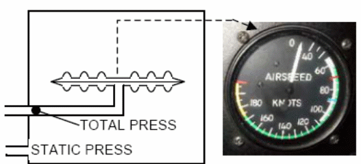
This is an instrument used to measure the speed of an aircraft, especially in knots. Generally, the pressure at the point of stagnation depends on fluid flow, atmospheric pressure, and velocity. This is described as follows: PT=P+ 1/2PV2.
This means that airspeed can be measured by dynamic and stagnation pressure. Therefore, airspeed readings depend on external pressure. The equation can be more intricate under incompressible conditions. However, the probability of deriving airspeed from stagnant and overall pressure is high (Department of Aerospace Engineering, 2004, p. 4). The airspeed indicator is a very responsive instrument that is able to gauge and punctually show the variation between dynamic pressure and the static pressure (Department of Aerospace Engineering, 2004, p. 5).
The dynamic pressure is based on the law of the pressure gradient. When the aircraft is on the ground, the atmospheric pressure and inert pressure are the same. The pressure increase is conveyed perfunctorily to the pointer. Each aircraft has a customized airspeed indicator. Therefore, the crew members should be aware of this instrument and should make use of it for safety reasons (Department of Aerospace Engineering, 2004, p. 5). The airspeed indicator is more or less similar to the Altimeter. The only difference is that the Air Speed Indicator makes use of both the static and dynamic pressures (Federal Aviation Administration, n.d., p. 2).
Vertical Speed Indicator
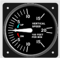
This instrument shows the speed at which the aircraft is rising or moving down. At the ground level, the instrument reads zero. Just like the Altimeter, this instrument mainly uses static pressure (International Virtual Aviation Organization, 2014, p. 8). The instrument is made up of a diaphragm enclosed inside an airtight casing. The diaphragm is mechanically connected to a needle and is vented to a stationary line with no constraint. The pressure difference is established between the instant pressure on the diaphragm and the cramped pressure in the casing (Department of Aerospace Engineering, 2004, p. 5).
Normally, the Vertical Speed Indicator reading is usually given at 6 to 9 second time lag. This allows the instrument to measure changes in pressure more consistently. The time lag is always granted due to pressure leaks in the system. The time lag sights a number of limitations in the use of this instrument. Instantaneous changes in the aircraft’s elevation often lead to erroneous reading. This is due to the oscillation of flow in the static ports.
Turbulent air can prompt an extension of the time lag. In addition, in case there is a blockage in the static port, the instruments will not show any result. For this reason, a number of aircraft always have an alternative vertical speed indicator to compensate for such errors (Department of Aerospace Engineering, 2004, p. 6).
Gyro Instruments
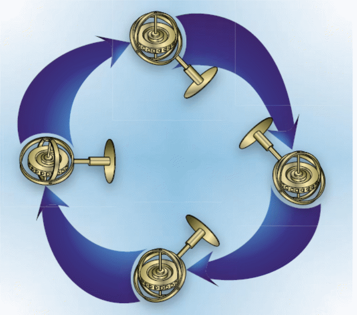
These are simply instruments that apply gyroscopic principles in their operations. A gyroscope is a spinning wheel whose axis is free to swing, but maintain a fixed direction unless disturbed (Department of Aerospace Engineering, 2004, p. 6). Gyroscope usually operates on two fundamental laws. The first law is the law of space obstinacy. This refers to the spinning of a gyroscope without changing position or direction. As the gyroscope gyrates, it stabilizes the frame. The second principle is the principle of precession, which is the movement or slanting of the wheel’s axis due to the applied force (International Virtual Aviation Organization, 2014, p. 4).
Figure 5 represents the tilts and turns of a mechanical gyroscope. Please note that despite the position of the gyroscope, the axis remains the same, that is, it upholds the law of space stringency. The aircraft instruments driven by gyro principles include position/attitude gauge, direction indicators, and turn controllers. These instruments help the pilot and the crew members to fly and steer aircraft safely (Pilot’s Handbook of Aeronautical Knowledge, 2007, p. 7).
Attitude Indicator
This is a gyroscopic instrument driven by a vacuum. To get a better understanding of how this instrument works, it is necessary to explore the vacuum gyro system. Figure 6 below provides an excellent representation of a characteristic vacuum gyro system.
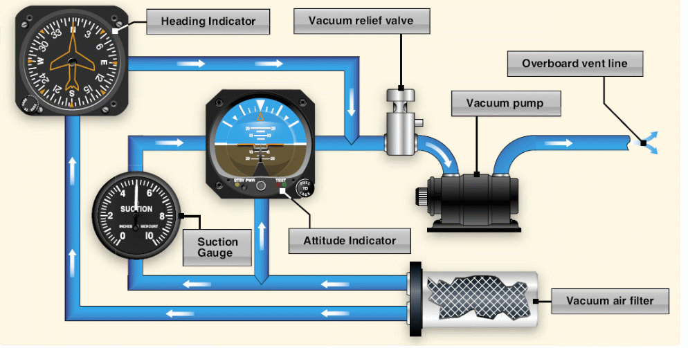
A characteristic vacuum gyro system is made up of the following components: a filter, gyroscope, sucking gauge, pressure regulator, and a space pump. The vacuum pump is driven by an engine and has an air exhaust. The air is sucked into the filter and then to the machines where it is discharged outside the aircraft. In the middle of the instrument is a regulator, which controls the speed at which the air enters the instrument. The pressure relief valve helps in averting extreme air suction, which could dent the nozzle and the engine by making the engine spin at a very speed (Pilot’s Handbook of Aeronautical Knowledge, 2007, p. 8).
The attitude indicator gives the pilot an immediate signal regarding the pitch and the angle of the aircraft relative to the horizon. It basically imitates the view that the pilots would have had if he/she is outside the windscreen, and there is no cloud or any other element to block the view.
Inside the attitude, an indicator is a gyroscope mounted on a contrivance of rings and pivots that the airplane can spin around for pitch and angle. A horizon disk is appended on a contrivance of rings and pivots to keep it on the same plane as the gyroscope and the aircraft’s pitch (Pilot’s Handbook of Aeronautical Knowledge, 2007, p. 9). Figure 7 below shows the front view and internal features of an attitude indicator.
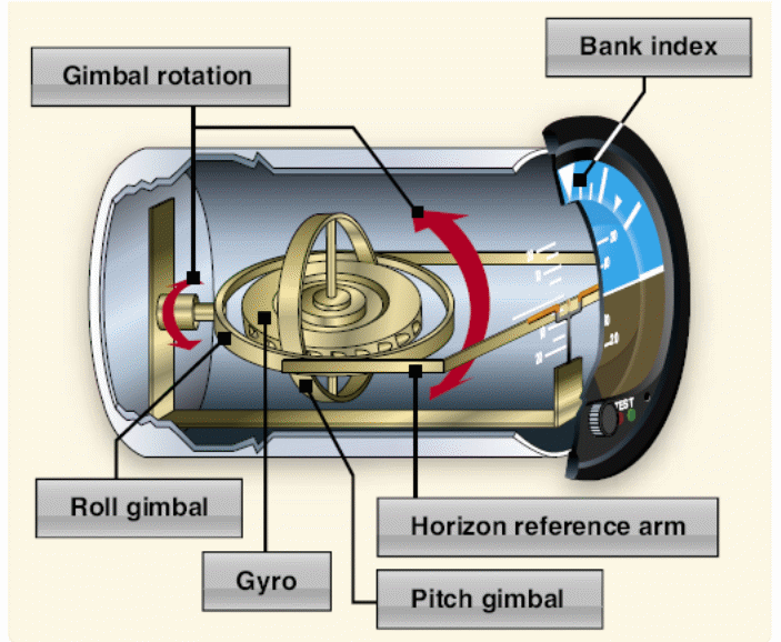
The attitude indicator’s principal operating mechanism is a gyro, which is a rotor disk that spins at approximately ten thousand revolutions per minute on a perpendicular axis. Even though the disk spins through a gyro vacuum system, it can also be operated through an electrical system. The gyroscope is designed for a 360-degree spin and an 85-degree pitch. The top half of the attitude indicator is calibrated.
The pitch increases by 5 degrees to a maximum of 20 degrees. Half of the frontal view of the instrument is blue, signifying the sky. The other half is brown, signifying the ground. The instrument can be affected by instantaneous acceleration or deceleration. Therefore, the instrument requires constant observation (International Virtual Aviation Organization, 2014, p. 4).
Heading Indicator
As already been mentioned, one of the laws that govern the gyroscope’s function is the law of space stringency. This refers to spinning without changing position or direction. The heading indicator’s operation is based on this principle. The force that resists spinning is used to move the compass card, which provides the aircraft’s direction. Unlike the magnetic compass, the heading indicator is not affected by the magnetic fields or spinning errors (International Virtual Aviation Organization, 2014, p. 7).
Turn Coordinator
Unlike other gyro instruments, turn coordinator is electrically driven. The gyroscope inside this instrument is placed crosswise and poised by a spring. The instrument also operates on the precession law to detect the bank angle. Airplanes are able to make a full circle turn within two minutes. This is usually known as the standard rate turn. Turn coordinators have two components, each providing different signals. The first components comprise of a diminutive aircraft, viewed from the rear. The diminutive aircraft has tick marks designating direct flight and full-circle turn.
The second component is the glide and skid indicator, which comprises of a cylindrical glass tube with a small sphere known as the inclinometer. They are found on the bottom part of the instrument. The slip and skid indicator alerts the pilot if when the aircraft gets out of the flight course (International Virtual Aviation Organization, 2014, p. 59). Figure 8 below shows a turn indicator.
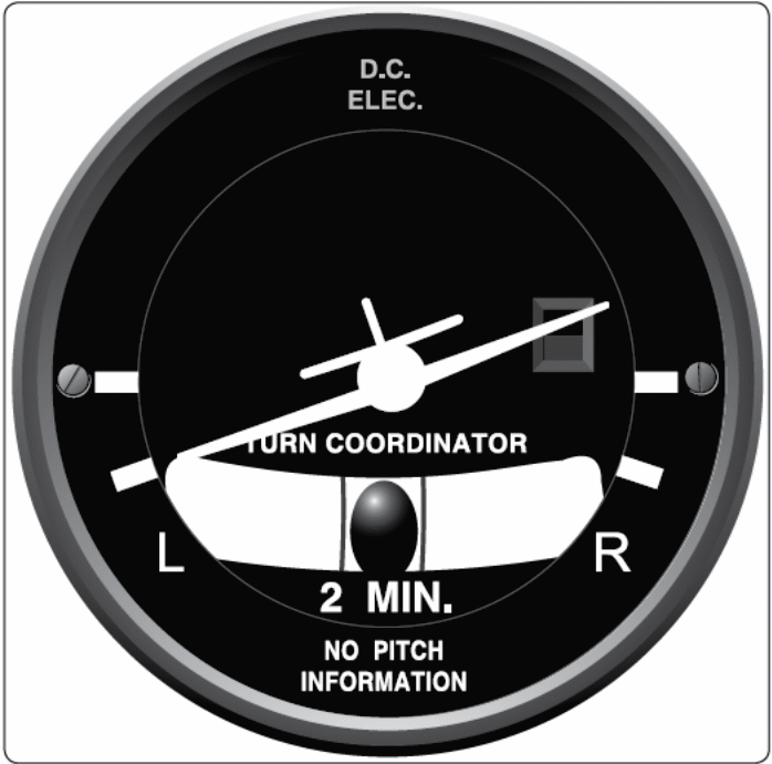
If the ball is at the center, then the aircraft is flying in a straight line. However, if the aircraft slides or glides, the spherical object moves to the left or right. The pilot must make use of the rudder pedals to steer the aircraft on the designated course. This is because uncoordinated flights normally lead to wastage of energy and excess consumption of fuel. In addition, they can lead to high stalling speed. Stalling speed refers to the ability of the aircraft’s wings to sustain flight earlier than usual, which is the cause of many aircraft accidents (International Virtual Aviation Organization, 2014, p. 60).
Aircraft Navigation Instruments and System
These are instruments and systems that help to determine where the aircraft is heading to. They include Magnetic Compass, Radar System, Automatic Direction Finder, Instrument Landing System, Autopilot System, Hyperbolic Navigational System, GPS, VHF Omnidirectional Range (VOR), Tactical Air Navigation System (TACAN), and the Distance Measuring Equipment (DME). We have already discussed the magnetic compass. Each of these instruments and systems performs different functions.
Automatic Direction Finder (ADF)
This one of the oldest aircraft instruments apart from the magnetic compass. This instrument automatically notifies the pilot when the aircraft is off the course through radio signals. The components of the Automatic Direction Finder include ADF receiver, control box, aerial, and direction indicator. The radio signals are in the low to medium frequency. The crew members can tune to any station and choose the mode of operation. The aerial receives the radio frequency, while the bearing points to the tuned station via the pointer (Department of Aerospace Engineering, 2004, p. 11).
Instrument Landing System (ILS)
This is one of the most vital aircraft systems. It provides perfect guidance to the landing aircraft. It utilizes two radio signals and power lighting to enable the aircraft to land securely. The system also helps the pilot to communicate with the ground systems. ILS comprises of localizer and the glide scope. The localizer provides tangential guidance, while the glide slope provides perpendicular guidance (Department of Aerospace Engineering, 2004, p. 12).
Autopilot System
This is one of the control systems. The control systems are based on accurate measurements and signals. An autopilot system is usually programmed by the pilot to ascend, descend, or maintain a certain altitude when heading to a specific destination. It includes an auto thrust function, which maintains a specific speed and power. This system cannot be used under 1000 feet following takeoff (Department of Aerospace Engineering, 2004, p. 15).
Radar
Radar worked by detecting the reverberation of radio signal pulse broadcasted by the station and reproduced by a target. The time lag from pulse transmission to reverberation is relative to the distance from the target. The main components of aircraft radars include an oscillator (generate radio frequency) and an aerial (receives frequency transmission) (Department of Aerospace Engineering, 2004, p. 10).
There are two types of radar, that is, primary radar and secondary radar. Primary radar is based on the ground and is used by air traffic control. On the other hand, secondary radar is air-based and complements the primary radar (Department of Aerospace Engineering, 2004, p. 11).
VOR/DME, TACAN, Hyperbolic Navigational System, and GPS
VOR stands for the VHF Omnidirectional Range. It works within a short-range and conveys the direction of the aircraft to the ground beacon. VOR is usually linked to the Distance Measuring Equipment (DME), which operates under the UHF band. DME estimate target distance.
Tactical Air Navigation System (TACAN) also works in the UHF band and performs the same function as VOR (Department of Aerospace Engineering, 2004, p. 12). The hyperbolic navigational system performs the same function as GPS. For that reason, it acts as a backup to GPS. They provide the most accurate global positioning data. They use radio signals from the satellites (Department of Aerospace Engineering, 2004, p. 16).
Conclusion
Aircraft Instruments and systems not only assist the pilots and crew members in navigating the aircraft, but also ensure the safety of the crew members and the passengers. They help the pilot to steer the aircraft on the designated course. This is because uncoordinated flights normally lead to wastage of energy and excess consumption of fuel. They also help the pilot and crew members to communicate with air traffic control. The above information has given us a deeper understanding of the aircraft instrumentation and systems.
References
Department of Aerospace Engineering. (2004). Flight Instruments and Navigation Systems. Milan: Polytechnic of Milan.
Edexcel Limited. (2009). Aircraft Instruments and Indicating Systems. Web.
Federal Aviation Administration. Flight Instrument Systems. Web
Ghosh, P., & Pant, P. (2010). In-flight Hypoxia-Still a Worrying Bane. IJASM, 54 (1), 6-12.
International Virtual Aviation Organization. (2014). Flight Instruments. Web.
Pilot’s Handbook of Aeronautical Knowledge. (2007). Flight Instruments. Web.