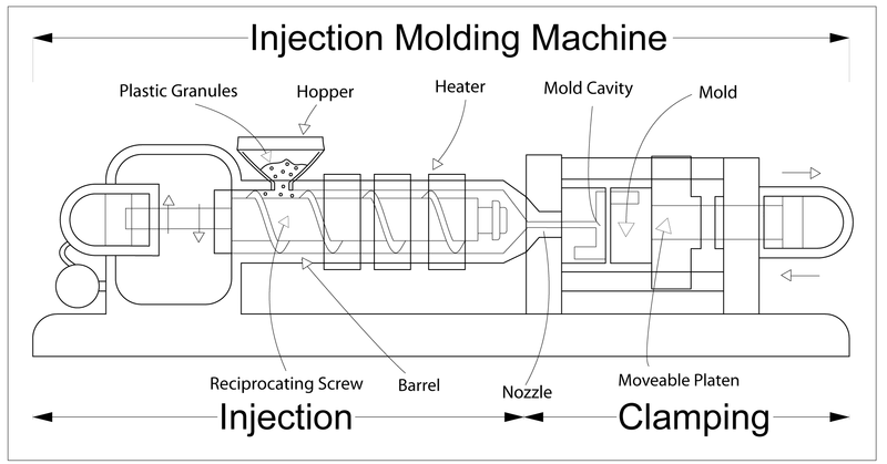
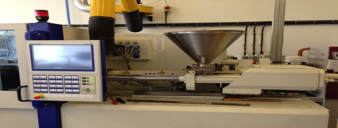
When it comes to the large-scale production of thermoplastic polymer parts, the injection molding technique dwarfs others. Furthermore, it is cost-effective. Basically, an injection molding machine constitutes two parts: an injection section and a clamping section (fig.1 and 2). The injection section has a hopper where a material is fed, and an injection ram that drives a molten material to the clamp thanks to heaters. At the clamping sections, various molds/die are used to produce desired shapes. The molds are manufactured from a range of materials including aluminum, steel, and beryllium-copper alloy. These molds are manufactured by either “CNC machining or by using electrical discharge machining process” (Malloy 32).
During injection, plastic granules are fed into a hopper which in turn feeds the heating barrel. The plastic granules are then driven by a screw plunger into a heating section where it melts to molten plastic. The molten plastic is then forced through a nozzle that leads into a mold cavity, eventually assuming the shape of the mold. On the mold, the molten plastic solidifies almost immediately owing to a maintained cold temperature.


To determine the effectiveness of a molding procedure then plastics must undergo tests. The specimen tested can be grouped into two: physical and chemical tests. The physical tests include tensile testing, impact weight, and molecular weight among others. On the other hand, the chemical test includes analytical testing of polymers among others. With regards to tensile testing, the analysis determines an extension limit vital in determining the material application. This is verified courtesy of the young modulus of a material.
Impact and molecular weight tests determine the resistance of a material to rupture. In particular, the latter determines the distribution of molecular weight thanks to temperature gel permeation chromatography (GPC). While the specimen’s thickness plays a part in determining the strength, material fabrication should not be overlooked.
The analytical test is a broad term that encompasses several tests including toxins, impurities, additives, and blends among many others. Hence, various chemical techniques apply including mass spectroscopy, thermogravimetry analysis, X-ray diffraction for polymers, and Composites among others. For instance, mass spectroscopy is used to determine the elemental quantitative analysis of a material.
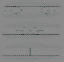
Akin to any other mechanical process molding process is synonymous with troubleshooting. Imperfections witnessed in finished products could either be due to the molds or may eventuate from the process. Some imperfections include weld line, stringiness, blister, and voids among others. When narrowing down to specifics, a weld line is simply a colorless line adjoining two fronts (fig. 3). This is caused by a poor temperature-time regime. Basically, the material temperature is set below an ideal, or less transition time is given to a mold between injection and transfer.

Stringiness is a string-like defect on a current model emanating from a previous shot. This may result from several reasons including too high a nozzle temperature, an unfrozen-off gate, poor positioning of heater bands in the barrel, and no sprue break among others.
A void is simply an enclosed air within an area of a mold. There are several reasons “that might contribute to this including limited holding pressure, too fast a filling process, and it happens at thicker areas especially at the bosses and the ribs (Malloy 25)”. Moreover, they do also happen where there is un-melt embedded within a melt pool.
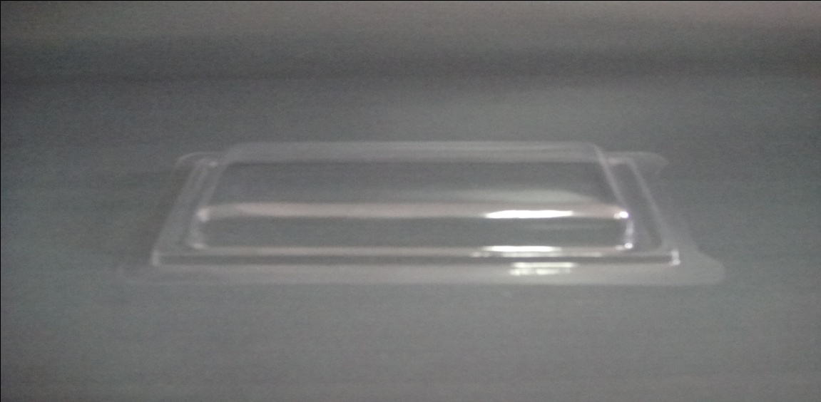
Finally, the blister is an imperfection defined by a raised part of a layered part on the surface of the mold (Fig. 4). This is caused by a process that the material is either too hot or there is a lack of a cooling unit.

Works Cited
Malloy, Robert. Plastic Part Design for Injection Molding. New York: Hanser, 1994. Print.