Introduction
Purpose
This laboratory work used Kirchhoff’s Circuit Laws (KCL) and Kirchhoff’s Voltage Law (KVL) to calculate simple closed electrical circuits involving only resistors and DC voltage sources.
Scope of Application
Only theoretical calculations were used in this work since no real voltages were measured with a voltmeter. In other words, the results obtained, as described below, may not be completely accurate since they do not consider any physical obstacles and errors that may have been observed in the experiment.
Theory
The theoretical basis for the experiment is the Kirchhoff electrical laws, which postulate the principles of current flow in closed loops. The benefit of using the KCL and KVL is the ability to calculate closed electrical circuits, including determining branch current and voltage values without the use of instrumental methods of measurement (ET). There are two Kirchhoff laws in physics: The first (KCL) shows that the sum of the currents entering and leaving the circuit is zero. The second Kirchhoff’s law, or KVL, reports that the algebraic sum of all voltages in a closed circuit must be equal to zero. This knowledge is sufficient to evaluate it on a practical problem-solving task.
Experimental Procedure
Schematics
Procedures
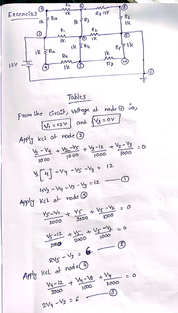
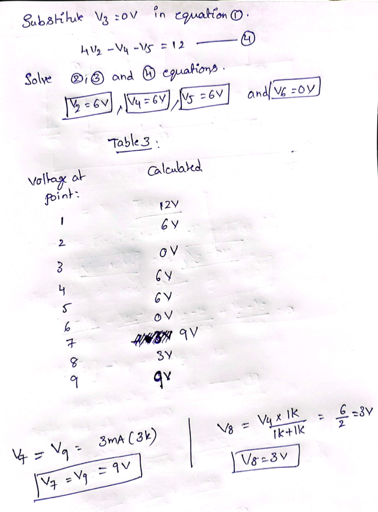
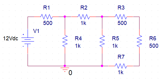
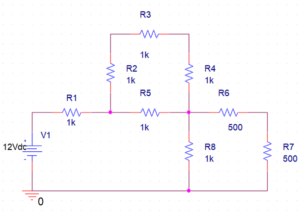
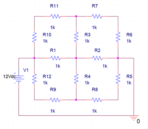
KCL and KVL laws were used to solve these circuits (Figure 1, Figure 2, and Figure 3). Specifically, calculations were performed for points on the circuits, and then equations were generated whose solutions determined the voltage or current values in the circuits.
Results
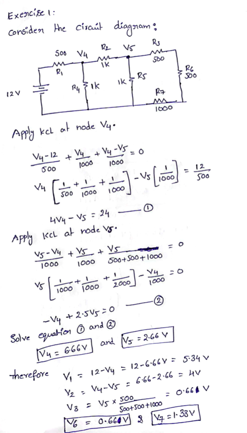
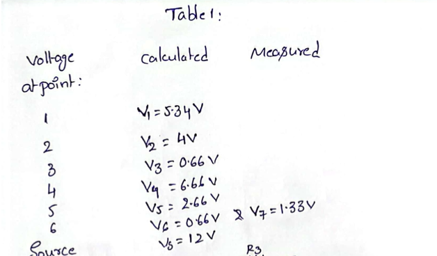
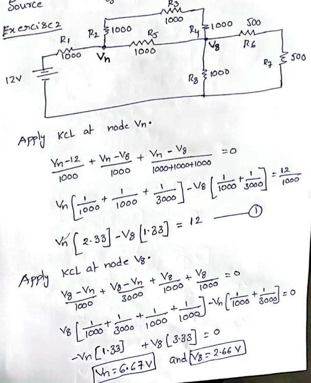
The results of the calculations performed, including original data and demonstration of solutions, are shown in Appendix A, Appendix B, and Appendix C.
Interpretation
KCL and KVL were used to calculate three different circuits as part of the three exercise solutions; the complexity of the circuits increased sequentially. Since there were no expected values since no direct measurements were made in this laboratory work, there was no opportunity to evaluate the reality of the results obtained in practice; only theoretical values were calculated. Nevertheless, all calculations (Appendix A, Appendix B, and Appendix C) showed that the laws KCL and KVL apply to a circuit of any complexity. However, it was noticeable that for circuits with more resistors, the total voltage was lower, confirming the idea of a relationship between voltage and active resistance in the circuit. The main problem in solving the problems was consistency since special attention was required for all currents entering and leaving the nodes. In addition, the solution required the use of mathematics to solve the equations, which could also be sources of error.
Conclusions
Based on the data obtained, the applicability of KCL and KVL for solving electrical circuits can be concluded. The calculations showed that the voltages at each point could be determined by solving the equations. It was confirmed that increasing the number of resistors in the circuit leads to a decrease in the total voltage of the circuit section.
Work Cited
ET. “Kirchhoff’s Circuit Law.”Electronic Tutorials, Web.
Appendix A
Original Solution Sheet for Task #1
Appendix B
Original Solution Sheet for Task #2
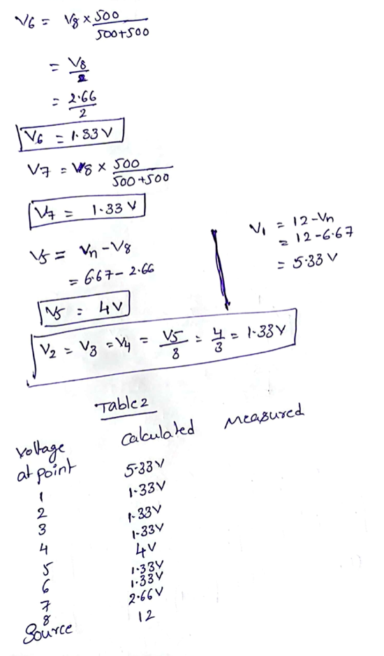
Appendix C
Original Solution Sheet for Task #3
