Measuring Rotational Torque Sensor Essay

Exclusively available on Available only on IvyPanda® Written by Human No AI

Summary

The objective of this paper was on one part to look on the basics of torque measurements, and on the other part to analyze how the latest generation of a digital telemetry works. On the first objective, we found out that the basics of torque measurements is depended on the nature of the torque (static or dynamic), and the mode of measurement (reaction or in-line). A combination of these factors determines the accuracy of your results. To the second objective, we were able to analyze how the latest version of telemetry works, and to this, we were able to carve out the advantages it had over its precursor technology. Basically, we found out that the rate at which the data is conveyed is extremely high, and the frequency feedback increased three folds more than its precursor to 3000Hz. Moreover, the gadget is fully software-driven, and one can shift ‘on-the-fly’ with the calibration remaining unaffected. Finally, we looked at the application of this technology and it was established that it is applied in a diversity of fields including medicine and meteorology among others.

Introduction

Background

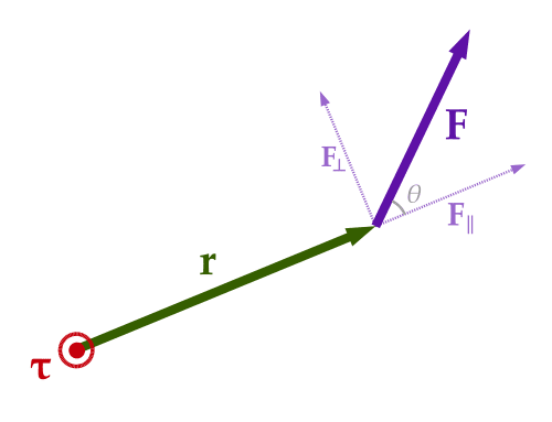
The science of measuring torque has come a long way with the equipment performing this function evolving into what the market offers today; more sophisticated equipment that are more efficient and accurate in their analyses. To the engineering fraternity and the likes, this term is not unique, however, to the rest; the question that abounds is: what is a ‘Torque’? In essence, it is vital that we define this term and hence explain its significance (Serway and Jewett 13). Simply put, torque is a gauge of the force that enhances a body to revolve. This can further be categorized as either reaction or rotational torque. Ideally, the former term is applied to bodies that are static; those that are not free to turn for example, the action of a screwdriver on a rusted screw. In the contrary, the later term is applied to bodies that are in free motion e.g. when a gear drives another gear in automotives. This science is fundamental in the sense that the horsepower and hence the efficiency of a machine can easily be determined (Tipler 70). Noteworthy, to determine this, another factor, rpm (revolutions per minute), comes in handy. In a nutshell, the efficiency of a machine can be enhanced further by optimizing on these two factors. This can easily be captured courtesy of the equation below:

  • hp = T*ω/ 63,025
  • ξ = hp0/hpi

Where; T, ω, ξ, hp0 and hpi denote the torque, revolutions per minute, efficiency, output and input horsepower respectively.

Torque measurement is “paramount in the engine and transmission testing, turbine and pump testing and testing of gear trains and power measurement within propulsion systems” (Schrand 1). In a synopsis, torque analysis is vital in determination of the efficiency of equipment e.g. electric motors among others. Some equipment, for instance, a lumber mill, “has the ability to instigate a change in the set of blades owing to the fact that it uses an encoded torque” (Okutani and Nakazawa 67). In effect, it improves on the efficiency while at the same time saves on the wear and tear consequently minimizing on the maintenance cost.

As it has been captured in the introductory paragraph, this technology has transformed to produce more sophisticated equipment with abilities unrivalled by its predecessors. Therefore, a brief history tracing back to where we were before to whatever we have today will give us a glimpse of what the future has in store for us. In a synopsis, this technology evolved from the slip ring, rotary transformer, analog telemetry, early and next generation digital telemetry in that order. The science behind “the slip ring technology was that its signals were derived from a rotating component through a static element to the signal detector” (Vuong and Madni 6). The demerit of this was that the dust generated in the due course was a hindrance to the transfer of signals. In effect, it was necessary that the dust be brushed off regularly to maintain its efficiency. This was rather cumbersome as the testing demand increased (Wells 54). To overcome this, a rotary transformer was developed. This could operate at high speeds devoid of wear and tear since it is a no-contact torque. Nevertheless, it could not withstand extraneous loading scenarios, for instance, bending instances. Moreover, its maintenance was demanding; it required the use of AC carrier activation equipment for signal conditioning. Overwhelmed by the demands of the testing requirements, the scientists resorted to using a wireless telemetry system (analog telemetry) composed of a sensor, radio transmitter, a source of power, and a signal receiver (Miller 4). With this, technology was shifting from mechanical to digital. However, even so, this one incorporated a number of receivers rendering it bulky. Moreover, its frequency feedback was restricted to 1000Hz. This prompted the think-tanks in the world of electronics to come to the rescue by developing a digital telemetry (Mayer 34).

Early digital generation telemetry was a near perfect relative to its predecessors; it allowed for bi-way communication stream. Nonetheless, because they were lacking in data processing capabilities, the discrete components that were incorporated functioned to add on the production costs. To cater for this, the next generation digital telemetry was developed (Multhauf 32). To its antecedent, a microchip was integrated vital in data management cum control and; hence, it reduced the bulkiness. Moreover, the accuracy, stability and resolution were greatly enhanced; the rate at which the data is conveyed is extremely high, and the frequency feedback increased by three folds to 3000Hz. Principally, these are considered to be “more than stand-alone sensors are complete torque measurement systems, with standard analog, frequency and digital outputs” (Schrand 1).

In a summary, the literature that follows will carve out the objective of this paper, and to preempt, this paper will partially focus on the basics of torque measurements, and partially look at the next generation digital telemetry. To the second element, the paper will focus on how the component functions, its merits and demerits, and the real life applications.

Objective of the Report

The main objective of this paper is biased towards the basics of torque measurements, and on the other part looks at how the latest generation of a digital telemetry works.

Next Generation Digital Telemetry

The basics of toque measurements

Ideally, the methods that are employed in the measuring of torques are classed as either static or rotational. Further, this can be narrowed down to either in-line or reaction. Vitally, a basic acknowledgement of the nature of the torque together with the variety of sensors available, one will be in a pole position to optimize on the acquisition of accurate data and a minimum cost.

Static versus Dynamic

In order to comprehend this, there is a need that we revisit the definitions of these two, the static and dynamic torques. In simple terms, as opposed to static, dynamic torque is a function of acceleration. Mathematically, this is summarized in Newton’s Second Law of motion as F= ma. A perfect example of this type as applied in the daily lives is the stopping of a car under motion (Kovacich and Kaboord 19). The force necessary to counter this is a function of the car’s mass and the acceleration. In this case, the acceleration is negative (deceleration). In the contrary, the force applied by the breaking pads to terminate motion is static, the reason being that there is no acceleration involved. Perfectly stated, a torque is basically a “rotational force, or a force through a distance” (Schrand 3). A scenario typified by an absence of angular acceleration results in a static torque. For instance, consider a set-up where a car is moving at a constant velocity, the torque as measured through the axle is a perfect example of a static torque. To this, we reckon that since the velocity is constant then there is no acceleration. Of note, in a machine, the factor determining the status of a torque is dependent on where the measurement is taken from (Kleppner and Kolenkow 109). For instance, in a car engine, when this is taken from the crankshaft the results would be majorly dynamic. This is in contrast to when it is taken from aforementioned example, axle.

Reaction versus In-Line

This kind of measurement is achieved by placing a torque sensor such that it comes between the torque assemblies. This is exhibited by the picture below:

Reaction versus In-Line

The logic behind this setting is to eliminate errors that might emanate in the course of measurement. The sources of these errors could be due to parasitic torques as generated from the bearings, superfluous loads plus the elements that have the potential of generating exceedingly large rotational inertia that might diminish the effects of dynamic inertia (Kane and Levison 67). Chiefly, to measure the dynamic torque, one needs to insert the gadget at the center of the torque assembly, crankshaft and the flywheel. As such, the losses arising from transmissions will be avoided, and also, the effects of rotational inertia from the flywheel will be decimated. When a sensor is inserted “between the hub and the rim” (Schrand 1), the measurement tested here is the static torque. In a summary, in-line measurements are basically meant to eliminate the effects of rotational inertia; hence, it represents a guide in the achievement of credible, dynamic torque readings.

A reaction torque sensor basically employs the “Newton’s Third Law which states that for every action, there is equal and opposite reaction force” (Schrand 2). Just like its name suggests, when measuring the torque, the idea here is that the parameter measured is the resistance to motion. Nevertheless, an in-line measurement can also be used here. The below image is an exhibition of how this can be achieved in a motor.

Reaction versus In-Line

A major drawback in this measurement is that in many cases, its function is dependent on the superfluous load which needs to be weighted on it (Halliday 45). The demerit in this is that it can introduce factors e.g. that may decimate dynamic loads of concern.

How a Next Generation Digital Telemetry Works

Aptly as it has been stated in the introduction, this represents the most recent telemetry. The achievements of this gadget have functioned to render its antecedent obsolete. This is basically an improvement of the ‘Early’ generation, coming with it a microchip, which eliminated the problems that were data management cum control. This gadget has a sealed sensor that is composed of a “rotor circuit board module” (Schrand 3). This enhances signal conditioning digitization notwithstanding. Antenna- caliper-style “coupling modules eliminate the need for hoop antennas and are more immune from vibration problems” (Schrand 3). From the manufacturer, the system comes when it is already tuned. The calipers and the antennae are shielded against the effects of moisture and oil. A signal-processing module on the other end receives the signals from the rotor component, displaying the results as obtained from the tested components (Doeblin 39).

Advantages and Disadvantages of the Next Generation Digital Telemetry

The advantages of this sophisticated gadget are that the accuracy; stability and resolution are greatly enhanced. Moreover, the rate at which the data is conveyed is extremely high, and the frequency feedback increased by three folds times more than its precursor to 3000Hz. The gadget is fully software-driven, and one can shift ‘on-the-fly’ with the calibration remaining unaffected. The microchip enhances maneuverability for it can be customized to fit a specific application. Moreover, it is cheap to maintain i.e. it is a “fit and forget” (Schrand 3). One disadvantage of this technology is that the sophistication that comes with it renders it rather expensive.

Real life application

Digital telemetry finds application in a diversity of fields. The advantage of this technology is that one can get data from a remotely located spot that would have been difficult to. Some of these applications include: in the meteorological studies where meteorologists implant it in the weather balloons and use it in data collection; space scientists have also used this technology to collect data, covering billions of kilometers; and in water management where information regarding the volumes and the quality of the same are conveyed. Importantly, telemetry comes in handy in medicine whereby data on the performance of a patient with an anomalous heart activity can be determined (Anderson 41).

Conclusion and Recommendations

To conclude this report, the objective of this paper which was partly to analyze the basics of torque measurements and, on the other part to look at how the latest generation of a digital telemetry works, was achieved. The report summarizes the path to the novel technology that has really contributed to a diversity of fields including meteorology and medicine among others. From these findings, I believe scientists can develop more advanced gadgets with greater frequency level than the one exhibited by the current system. This would increase the rate at which data is received and hence the efficiency.

Works Cited

Anderson, Norman. Instrumentation for process measurement and control. Sydney, Australia: CRC Press, 1998. Print.

Doeblin, Earnest. Measurement systems application design. Berkshire: Mcgraw Hill, 1966. Print.

Halliday, David and Resnick Robert. Fundamentals of physics. New York: John Wiley & Sons Inc, 1970. Print.

Kane, Thomas and Levison David. Dynamics, Theory and Applications. New York: McGraw Hill publishers, 1985. Print.

Kleppner, Daniel and Kolenkow Robert. An introduction to mechanics. New York: McGraw Hill publishers, 1973. Print.

Kovacich, James and Kaboord Begale. Method of manufacturing a piezoelectric torque sensor. Washington, DC: Washington Press, 2002. Print.

Mayer, Chalfant. Trends in Aeronotical Flight Test Telemetry. New York: McGraw Hill, 1998. Print.

Miller, Tom. Telemetry: Summary of concept and ationale. Washington: Washinton press, 2011. Print.

Multhauf, Robert. “Contributions from The Museum of History and Technology.” The introduction of self-registering meteorological instruments (1961): 95-116.

Okutani, Akio and Nakazawa Yuji. Torsion angle detection apparatus and torque sensor. New York: McGraw Hill, 1993. Print.

Schrand, David. Basics of Torque Measurement. New York: John Wiley & Sons Inc, 2008. Print.

Serway, Raymond. and Jewett John. Physics for scientists and engineers. New York, NY.: Brooks Cole, 2003. Print.

Tipler, Paul. Physics for scientists and engineers: Mechanics, Oscillations and Waves, Thermodynamics. Manchester: Freeman publishers, 2004. Print.

Vuong, Roch and Madni, Marlin. Differential capacitive torque sensor. Manchester: McGraw Hill publishers, 2004. Print.

Wells, Mayo. The origins of space Telemetry: Technology and culture. New York: New York publishers, 1963. Print.

Cite This paper
You're welcome to use this sample in your assignment. Be sure to cite it correctly

Reference

IvyPanda. (2022, May 15). Measuring Rotational Torque Sensor. https://ivypanda.com/essays/measuring-rotational-torque-sensor/

Work Cited

"Measuring Rotational Torque Sensor." IvyPanda, 15 May 2022, ivypanda.com/essays/measuring-rotational-torque-sensor/.

References

IvyPanda. (2022) 'Measuring Rotational Torque Sensor'. 15 May.

References

IvyPanda. 2022. "Measuring Rotational Torque Sensor." May 15, 2022. https://ivypanda.com/essays/measuring-rotational-torque-sensor/.

1. IvyPanda. "Measuring Rotational Torque Sensor." May 15, 2022. https://ivypanda.com/essays/measuring-rotational-torque-sensor/.


Bibliography


IvyPanda. "Measuring Rotational Torque Sensor." May 15, 2022. https://ivypanda.com/essays/measuring-rotational-torque-sensor/.

If, for any reason, you believe that this content should not be published on our website, you can request its removal.
Updated:
This academic paper example has been carefully picked, checked, and refined by our editorial team.
No AI was involved: only qualified experts contributed.
You are free to use it for the following purposes:
  • To find inspiration for your paper and overcome writer’s block
  • As a source of information (ensure proper referencing)
  • As a template for your assignment
1 / 1