The objective of this experiment is to verify the principles of moments for both parallel and non-parallel forces.
Theoretical Background
The ‘Principles of Moments’, also referred to as ‘Variignon’s Theorem’, is a vital principle in resolving a system of forces plying on a given structure. Together with the ‘Principle of Transmissibility’, the principle of moments determines the stability of a given structure. According to Putman (2), the principles of moments states that “the moment of any force is equal to the algebraic sum of the moments of the components of that force” (Putman 2). By definition, the moment of a force (F) is the turning effect of that force. The moment of a force is a vector quantity plying on a rotational system at a radius (d) from the axis of rotation.
Therefore:
- Moment= Force (F)*perpendicular distance(d).
- The SI units for moments is Newton Meters(NM).
From the expression above, it is evident that the moment of a force is directly proportional to the force and the perpendicular distance between the line of action and the force. Hence, the turning effect of a system of lever increases with the duo of the Force F and the distance d.
The principle of moments of a body at equilibrium states that the sum of clockwise moments about a point is equal to the sum of anticlockwise moments about the same point (Hibbeler 48). This can be represented by the figure 1 below:

Clockwise moments (C.M)= Anticlockwise moments (A.C.M)
i.e. M1d1= M2d2
When counter moments are equal, the system does not rotate thus, the system is said to be at equilibrium.
Experimental Procedures
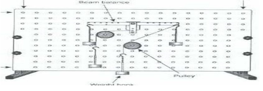
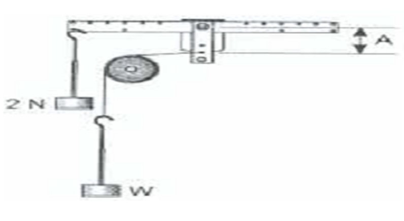
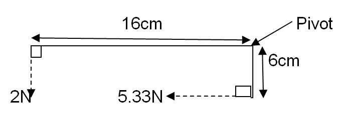
A mounting panel in a vertical position was mounted perpendicularly on a flat ground surface with a horizontal bar mounted on it centrally at a pivot. Masses were then suspended on either sides of the bar; one at a time at different angles courtesy of the pulleys while holding the left hand side weight and the distance constant at 2N and 160mm respectively to bring the lever at equilibrium (Fig 2 below). The masses on the right hand side of the lever was later on suspended from the lower arm to bring it to equilibrium position (Fig 6). At equilibrium positions, the perpendicular forces, resolved forces (when the line of action is at an angle), and the perpendicular distances were taken into account when calculating the moments. In total, four tests were carried out as shown in the figures below.
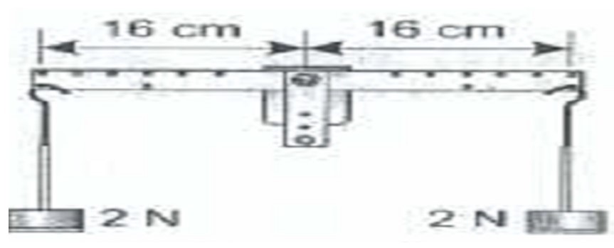
Test 1 (Fig 3) – of a 2N weight at equilibrium with a weight of 2N at 16cm from the pivot.
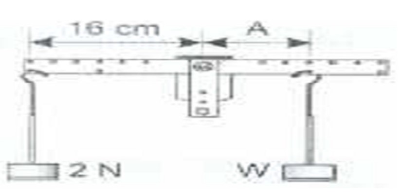
Test 2 (Fig 4) – of weight W at a distance A in equilibrium with a 2N weight at 16cm from the pivot.
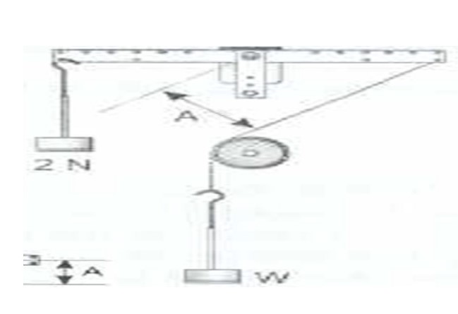
Test 3 (Fig 5) – of weight W acting at a distance A from the pivot and in equilibrium with a 2N weight at 16cm from the pivot.
Test4 (Fig 6)- of weight W suspended from the lower arm and in equilibrium with a 2N weight at 16cm from the pivot.
Experimental Data
Data Analysis
Moments= Force(F)* Perpendicular distance (d) between the pivot and the line of action (Putman 5).
Test 1:
At equilibrium state;
the sum of clockwise moments (C.M)= the sum of anticlockwise moments (A.C.M)
2*1.6 NM= 2*1.6NM
3.2NM= 3.2NM
Test 2:
At equilibrium;
C.M= A.C.M
C.M= 10* 3.2= 3.2NM
A.C.M= 2*1.6= 3.2NM
Therefore, C.M= A.C.M
Test 3:
At equilibrium;
C.M= A.C.M
Therefore, basing on the fig 7 below of how the forces have been resolved we obtain:

Sin β= 11.5/16
β= 45.95°
α= 90°- 45.95° = 44.05°
cos 44.05°= x/ 2.78°
x= 2.78 cos 44.05°=1.998N
C.M= 1.6* 1.998= 31.968NM≈ 3.2NM
A.C.M= 1.6*2= 3.2N
Therefore, C.M is equal to A.C.M
Test 4 (Fig 8): At equilibrium,
C.M= A.C.M
C.M= 1.6* 2= 3.2NM
A.C.M=5.33*0.6= 3.198NM≈ 3.2NM
Thus, C.M is equal to A.C.M
Discussion
The experimental objective was to verify the principles of moment which states that when a body is at equilibrium, the sum of clockwise moments about a point is equal to the sum of anticlockwise moments about the same point. The experimental results augur well with the theoretical principle provided that the line of action of the forces, and the distances between the pivot and the lines of action meet at right angles. This can be attested from the analysis above whereby; when the force is acting at an angle, one can either choose to resolve the forces or the distance. For the case above, the force was resolved. At equilibrium position, each test revealed that the clockwise moment (3.2NM) at a point is equivalent to the anticlockwise moment (3.2NM) about the same point.
It is also evident from the tests that the principles of moments hold irrespective of the shape of the body. This is shown in the final test whereby what matters is the relationship between the lines of action of the forces and the distances from which they act from the pivot. The two should meet at right angles for the principle to hold.
Conclusions
The aim of the experiment which was to verify the principle of moment for both parallel and non-parallel forces was successfully achieved. The findings revealed that in deed at equilibrium position, the sum of clockwise moments about a point is equal to the sum of anticlockwise moment about the same point. The principle holds irrespective of the direction of the force or the shape of the beam.
References
Hibbeler, Russel. Technology and Engeneering. Columbus, Ohio: Prentice Hall, 2009. Print.
Putman, Matthew. Torque and Principles of Moments Web.PutmanMedia electronic newsletter, 1994. Web.