Physical Layer
Physical layer
This is the first layer in the OSI model. It refers to a layer that outlines electrical devices along with their design characteristics. Its main function is to outline links, which lie between transmission media and devices. These transmission means include optical cables as well as copper, among others (Spurgeon 156). In the recent past, this layer has been closely linked with the Data Link layer, even though it emphasizes interaction that exists between a medium and a single device.
The devices include voltage cables, pin-layout, repeaters, and adapters that may be utilized in networking, among others. As has been stated above, the physical layer links a medium with a single device. In addition, the Physical layer is considered as the lowest of all. The physical layer performs several functions namely, establishment as well as the termination of links between communication media. This helps in allowing communication between devices in the physical layer. The physical layer also performs other functions that include defining hardware specifications, signaling as well as encoding, among others.
In addition, the Physical layer conducts the transmission of data as well as its reception. It is quite important to note that the physical layer forms the main domain for network designs that relate to hardware. This is sometimes known as topology and design. In essence, the physical layer deals with issues that entail the defining of connectors, network interface, among other hardware devices. In addition, it transforms into signals, data, which is in bits. Essentially, the physical layer is usually abbreviated as “PHY” and is considered important because of its functions. Moreover, Data can only be physically moved via network interface through a physical layer (Kozierok 1).
The physical and logical circuits in networking
Physical and logical circuits describe the kind of network topology used in networking. Network topology can be defined as a layout of patterns or interconnections consisting of different elements, nodes, or links in a computer (Breyer and Riley 107). The topology network is divided into two categories namely physical and logical topologies or circuits (Kozierok 1). Physical topologies or circuits are designs of networking that are tangible and consist of devices, installation of cables as well as location. On the other hand, logical topologies refer to a process of data transfer through a network. In essence, logical topology usually links with a basic network as opposed to a physical network that links to the core network (Tanenbaum 274-275).
Multiplexing
Multiplexing refers to a process by which multiple digital or analog signals are conglomerated into a single signal via a shared network. Multiplexing is sometimes known as muxing and is widely utilized in computer networks as well as in telecommunication. This is usually utilized for digital streams of data as well as analog multiple message signals. A sheer example of the same in telecommunication is commonly observed when making multiple telephone calls through a single wire.
This kind of transmission is usually done through communication media (Stallings 137-138). The latter can be a physical communication medium. It is quite important to note that multiplexing divides the low-level channel of communication into various high-level channels of communication. These are commonly known as high-level logical channels. The logical channels are made in such a manner that each relates to either data or message signal.
On the other hand, for one to get original channels, through the receiver, the reversal process must be done; this process is usually referred to as demultiplexing. In addition, multiplexing is commonly utilized in data networks. This is usually done to enable the sending of multiple data from multiple or many sources via a single line known as the physical layer. Besides, multiplexing is always used in concurrence with dark fiber, along with SONET (Rodriquez 1).
Importance of multiplexing
Multiplexing has been utilized for decades. It has been applied in the sending and receiving of multiple packets or segments of data. In essence, this has also formed its main objective, which is to send data through a single layer or physical layer. Multiplexing is quite popular in this regard since packets of data can be sent over a single physical layer. Its use has widely been witnessed in telephone networks and this was mainly done to transmit speech conversations through a twisted wire (Kozierok 1).
Types of multiplexing
There exist many types of multiplexing; these include time-division multiplexing (TDM), dense wave division multiplexing (DWDM), as well as frequency division multiplexing (FDM). FDM multiplexer was mainly utilized in the early telephone network systems; this was done to enable the division of frequencies to support many users. For instance, 5 users would be given a single physical line over a standard sound spectrum.
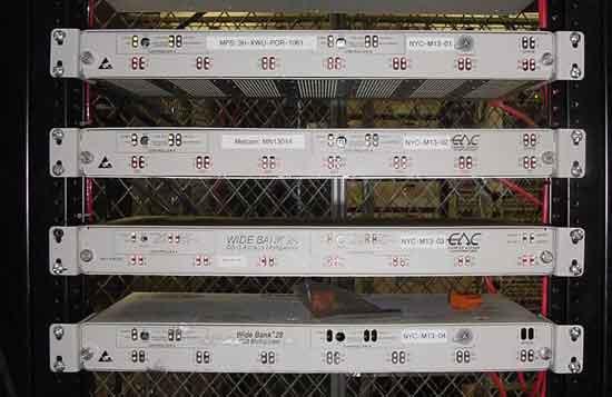
This is nowadays utilized in TV cables as well as FM Radios. Moreover, it is still employed in the older generation cellular systems, which apply analog circuits. The following diagram provides an example of a DS3 multiplexer (Kozierok 1).

TDM, which is another type of multiplexer, was developed much later, during the emergence of digital technology that occurred in the late 1950s. Its main difference from FDM is that users get all frequencies for some time as opposed to FDM where users get some frequencies at all times. TDM converts the analog signal into a digital signal. In this regard, it allows multiple data to be sent through a single physical layer and in addition, offers better quality as compared to FDM. It is quite important to note that TDM is categorized into two main flavors, Statistical and Synchronous TDM (Stallings 137-138).
The former is very complex and provides efficiency. On the other hand, the latter is extensively used in conjunction with ISDN as well as T carriers. Lastly, DWDM, which is commonly known as the wave division multiplexing, was made as a modification of FDM and TDM. Its use is the same as other multiplexers even though in this case it utilizes colored lasers to send many channels through a single physical layer. It has numerous advantages, which include the fact that it combines several connection types namely OC and ATM, among others (Rodriquez 1).
Wavelength Division Multiplexing
DWDM multiplexer, which is universally known as wave division multiplexing was made as a modification of FDM and TDM. DWDM and FDM are similar in that they both divide frequencies into channels. However, they differ in the mode of transmission as DWDM uses a colored laser as opposed to FDM. Its use is the same as other multiplexers even though in this case it utilizes colored lasers to send many channels through a single physical layer.
It has numerous advantages, which include the fact that it combines several connection types namely OC and ATM, among others. The main disadvantage it presents to users is that it runs only on fiber optic cables. In addition, the method utilized in DWDM is very complex since several channels can be sent over a physical layer using a colored laser (Stallings 137-138). DWDM is the latest of all multiplexers and forms the most convenient and efficient way of sending packets of data over a physical layer.
Moreover, the method utilized in DWDM is very complex since several channels can be sent over a physical layer using a colored laser. DWDM was very expensive before a special laser that could be tuned from one color to another emerged. This was brought in to solve the problem of using a single color for transmission (Rodriquez 1).
Physical Layer Data Encoding
The Manchester encoding scheme used for transmitting digital Signals with Ethernet
Encoding techniques are usually utilized in sending or transporting digital bits over carrier waves. There exist several techniques, which offer various advantages, as well as disadvantages, which are in respect to each other. Therefore, depending on one’s prerequisites for transmitting digital bits, a choice may be made from several encoding techniques. These include, Baudot, binary coded decimal, which is also known as BCD, (ASCII) American Standard Code for information interchange, (EBCDIC) Extended Binary Coded Decimal Interchange Code, and Manchester Phase Encoding, among others (Stallings 137-138).
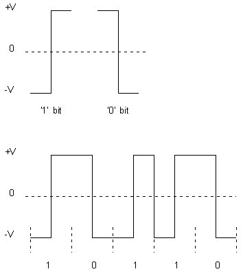
There are two types of Manchester encoding schemes, these are MPE and DME, which are Manchester Phase encoding and Differential Manchester Encoding respectively. Amongst them, the scheme that is commonly utilized in transmitting digital signals in Ethernet is MPE. For instance, it is utilized in 802.3 Ethernet. The Manchester Phase Encoding works in this manner: A data bit ‘1’, which comes from the level-encoded signal is conveyed by the full cycle of a signal that is usually inverted from a master clock.
The master clock must match a phase rise from ‘0’ to ‘1’ of a phase-encoded signal. This gives a –V and +V in the first and second half respectively. On the other hand, when a data bit ‘0’ emerges, the level-encoded signal is conveyed by the full cycle of a signal that is usually inverted from the master clock. This master clock must match a phase fall from ‘1’ to ‘0’ of the phase-encoded signal. This gives a +V and -V in the first and second half respectively.

MPE operates as illustrated in the diagram above. The lower diagram showcases an example of encoding a digital bitstream such as 10110. In MPE, synchronizations of both the receiver and sender are made possible by a transition between the bits (Haden 1).
The physical layer-encoding scheme used in token ring networks
Encoding techniques are usually utilized in sending or transporting digital bits over carrier waves. There exist several techniques that offer various advantages as well as disadvantages, which are in respect to each other. Therefore, depending on one’s requirements in transporting digital bits, one or more encoding techniques may be applied. These include, Baudot, binary coded decimal, which is also known as BCD, (ASCII) American Standard Code for information interchange, (EBCDIC) Extended Binary Coded Decimal Interchange Code, and Manchester Phase Encoding, among others (Stallings 137-138).
In essence, the physical layer encoding scheme, which is usually employed in token ring networks, is known as the differential Manchester encoding scheme. This scheme is sometimes abbreviated as DME. In the differential Manchester encoding scheme, a ‘1’ bit is usually indicated when made in such a way that the last half of a previous signal equals the first half. On the other hand, a ‘0’ bit is usually shown when made in such a way that the last half of a previous signal equals the opposite of the first half (FitzGerald and Dennis 23).
It is also important to note that a transition always exists in the middle of a bit-time. This happens in all cases whether it is derived from a low to high or a high to low. Clock synchronization in DME is usually ensured with a voltage change during each bit of transmission. For this reason, Token rings utilize DME as opposed to Manchester encoding which uses Ethernet (Haden 1).
The data-encoding scheme used with Ethernet 100Base-T for transmitting data over cat 5 cables
There are different ways of Transmitting data from large bits per second. This can be done using encoding schemes such as MLT-3 (Multi-level transition 3) and 5B/6B, among others (WildPackets, Inc. 1). MLT-3 utilizes a multilevel amplitude to perform frequency signaling. This involves patterns of combination, for instance, when one wants to encode 8 bits, and then there are 28 codes, which equals 256. The scheme allows 5-level signals to be used (Stallings 137-138).
These schemes work in the same manner as PAM-5 (Pulse Amplitude Modulation). 5B/6B encoding also provides a continuous 100Base T transfer. It has an error checking capability that ensures the efficiency of output. This allows for the detection of excess zeros and ones. The scheme works by encoding 5-bit data patterns into 6-bit data patterns (Haden 1).
MLT-3, which transmits 100Base T, is a scheme that was brought up by the ANSI X3T9.5 committee. It utilizes 31.25MHZ to attain 100MB/s. UTP is usually on the low pass, and hence hinders frequency signals of high magnitude. This problem in UTP led to the exploration of new methods that could transmit larger data packets. It is in this regard that MLT-3 emerged (FitzGerald and Dennis 23). Manchester encoding could not be used for obtaining 100Base T, since its frequency was significantly low. For instance, MPE has a master clock that runs at 10 MHz, instead of 125 MHz usually required by 100Base T. Patterns involved are 1, 0 -1, and 0.
For instance, when the data signal gives a ‘1’ then its output transitions to another bit that follows the pattern. For example, if the indicated bit were ‘0’, then the subsequent data signal would be ‘0’ since there is no transition. MLT-3 gives a cycle length, which is a quarter of MPE encoding. This provides a signal peak of 31.25, which is in accordance with FCC regulations. It is quite essential to note that MLT-3 encounters various issues in a series of ‘1’ and ‘0’, among others. This makes local circuitry to employ a free running clock in counting bits as opposed to checking clock synchronization from the data transmitting source. This problem can be solved by using FSR (Feedback Shift Register) (Haden 1).
Pulse Amplitude Modulation-5 (PAM-5) used in Gigabit Ethernet (1000Base-T)
Transmission of large bits per second can be done using encoding schemes such as PAM-5 (Pulse Amplitude Modulation), among others. PAM-5 utilizes multilevel amplitude to perform frequency signaling (Wild Packets, Inc. 1). This involves patterns of combination, for instance, when one wants to encode 8 bits, then there are 28 codes equaling to 256. This scheme allows 5-level signals to be used. The schemes work in a similar way as MLT-3 (FitzGerald and Dennis 23).
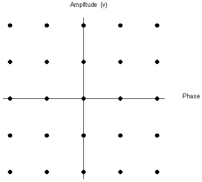
PAM-5 encoding schemes are quite discreet and this can be observed when a graph of time against voltage is plotted. This gives an ‘eye pattern’ effect with different signal levels. In this case, other techniques are usually employed to help in detecting and correcting errors. These techniques include Trellis coding, among others. Trellis coding employs Viterbi decoding in order to perform error detections as well as their corrections. In order to obtain 1000 Mbps, 2 bits in PAM-5 is usually represented by one symbol. Each symbol rate has a rate of 15Mbps, which occurs in pairs and in each direction. When these are summed up, the total rate is 1000Mbps. The diagram below illustrates a PAM-5 (Pulse Amplitude Modulation) encoding scheme.

PAM-5 encoding scheme is generally utilized by Gigabit Ethernet. The scheme provides data signals that have measurable phases and amplitudes with respect of the marker signal. Moreover, these signals are discrete. In essence, more data bits per cycle can be transmitted using PAM-5. PAM-5 (Pulse Amplitude Modulation-5) is therefore the most appropriate encoding scheme for Gigabit Ethernet (1000Base-T) (Haden 1).
Works Cited
Breyer, Robert, and Riley, Sean. “Switched, Fast, and Gigabit Ethernet”. Macmillan Technical Publishing, 1999, p. 107.
FitzGerald, Jerry, and Dennis, Alan. “Business Data Communications and Networking, 10th Edition”. Indiana: Wiley Press, 2009.
Haden, Rhys. “Data Encoding Techniques”. Data network Resource. 2007. Web.
Kozierok, Charles. “Physical Layer (Layer 1)”. The TCP/IP Guide. 2005. Web.
Rodriquez, Eric. “Multiplexing”. Skullbox.Net. 2011. Web.
Spurgeon, Charles. “Ethernet the Definitive Guide”. O’Reilly Media, 2000, p. 156.
Stallings, William. “Data and Computer Communications (7th ed.)”. Prentice Hall, 2004 pp. 137–138. Web.
Tanenbaum, Andrew. “Computer Networks (4th Edition)”. Prentice Hall, 2002, pp. 274–275. Web.
WildPackets, Inc. “Fast Ethernet Encoding Schemes”. Wild Packets. 2011. Web.