Sliding bubble dynamics can be characterised by the effects of various forces that act on the bubble while it slides along the surface of an inclined plate. Figure 8 shows the force balance of a bubble sliding underneath an inclined plane. The most important factors that affect the fundamentals of a sliding bubble are the effects of surface tension, buoyancy, as well as drag. Buoyancy comprises several components out of which the x-module exerts a force that acts in the same direction as the surface of the plate. Consequently, the bubble glides. On the other hand, the y-module of the force of buoyancy exerts its force at a 90o angle to the surface of the plate thereby compressing the bubble [1].

In general, when the bubble rises in a viscous fluid freely, the surface tension force attempts to maintain the initial spherical shape of the bubble while buoyancy forces the bubble to rise in the direction of the gravity vector. Drag forces exert their impact in the opposite direction of the motion of the bubble and are primarily due to adverse pressure gradients. Pressure drag increases with the bubble frontal cross section area and the rise or slide velocity.
Theory of Bubble Attached to the Solid Surface
The Static Contact Angle
An expression denoting the static contact angle (θs) was first derived by a scientist known as Young in the year 1805. A static contact line is shown in the Fig. 14, which illustrates an interface between two fluids. Each interface has a constant surface tension.

The horizontal force balance yields the Young-Laplace equation.

The static contact line is usually referred to as the three-phase contact line. The dislodgement of an immiscible fluid by a different fluid down a solid support is referred to as dynamic wetting. This phenomenon leads to the formation of a shifting contact line. The shifting contact line is a boundary whose position with respect to the solid support alters as time progresses. The resultant contact angle is referred to as a dynamic contact angle [31].
Figure 15 shows that the contact angle is a straightforward gauge of the ability of a surface to become wet. A contact angle that measures 0º shows that the surface is fully water-loving (hydrophilic), while an angle that measures 180º implies the surface is water-hating (hydrophobic). Contact angles that are smaller than 90º imply that water causes the solid to be wet. Conversely, contact angles greater than 90º show that there is a strong attachment between air and the solid.

For Young’s equation to hold (equ. 17), it is mandatory that certain conditions are maintained. For instance, the solid support must be level, even, uniform, static, unreactive, and impermeable. In addition, the surface should not be deformed by external forces. However, existent surfaces do not always satisfy these conditions [32-35]. Therefore, comprehending the basics of surface chemistry as well as wettability affects the contact angle as well as the management of the bubble and surface tension. The latest study [36] reveals that bad wettability influences the shape of the bubble substantially causing it to form a shape other than the conventional spherical shape because of the twisting and broadening of the bubble edges on the solid support. A number of investigational procedures can be employed in the quantification of the ability of a surface to become wet (wettability). Such procedures include the determination of the contact angle, partitioning into two phases, microflotation, bubble hoisting, as well as vacuum floatation. The underlying principle of these techniques is that wetting of surfaces occurs as a result of the dislodgement of oil on a solid support [37].
Effects of Various Forces on the Bubble Forming under the Horizontal Surface
Literature shows that the shape of a bubble beneath or on top of a solid support exhibits an obvious discrepancy [38] because of the variations in the direction of forces exerted on the bubble. The magnitude of the contact angle formed when a bubble attaches to a horizontal solid support influences how big a drop or bubble can be [39]. The subjection of the bubble to additional forces from a flow field alters its size. For instance, if the forces are focused away from the plane, the volume of the bubble reduces because the detachment conditions are met. Conversely, focusing the forces in the direction of the surface, in the absence of other forces increases the size of the bubble.
Overall, bubbles spawned beneath a horizontal surface enlarge because of coalescence, become compacted owing to the perpendicular buoyant field [39] and are inclined to sliding if the surface is flat. The most important forces that have noteworthy consequences on the sliding bubble dynamics include forces of buoyancy, surface tension and drag. Perron et al. [38] outline the form and height of a static bubble beneath a horizontal surface as shown in figure 16.


Two distinct systems of movement may arise following the attachment of a bubble on a surface that contains a dry spot provided that the force of buoyancy prevails over the impeding surface tension forces. As a general rule, there is a crawling movement followed by the motion of the bubble on a wetting layer that disconnects it from a solid surface. The disturbance of the state of equilibrium leads to the development of a wetting layer. This disturbance may be as a result of joining of the triple line due to a chemical contamination or a surface default at the tip of the bubble leading to the distortion of the bubble and a decline in the extent of the surface tension force. Thereafter, the least velocity required for the formation of the liquid layer is attained causing the bubble to slither on the layer. It is realized that the speed of a moving bubble on a wetting layer surpasses the terminal velocity of a crawling bubble by one order of magnitude [38]. For crawling bubbles at a specified angle of inclination, larger bubbles exhibit slower velocities and vice versa. When the volume of the bubble surpasses a given value, the bubble can move on the entire surface of the wetting layer.
A set of equations describing the interface of gas bubble with the surrounding liquid is derived [40] in which the effects of gravity, surface tension and contact angle are taken into account.


In the above equations, H denotes the curvature and t and n are tangential and normal directions of the interface. The numerical and the experimental results are compared in Figure 17, Peng et al. [40].

Theory of Bubble Formation and Detachment
At a relatively lower flow rate, the size of the bubble mainly depends on drag and surface tension force. Drag is exerted by the flowing fluid while surface tension force keeps the bubble adhered to the orifice. The modelling procedure of the bubble formation is quite complex due to several parameters. The list of assumptions that have to be made for modelling the bubble formation is listed in the appendix-I [18].
The advancement of a bubble entails two key stages identified as the expansion phase and the detachment phase as illustrated in figure 1 [19]. The diverse forces that are exerted on the bubble are [19]:
Buoyancy Force

Force Due to the Momentum

Surface Tension Force

Drag Force

Inertial Force

Excess Pressure force


Formation process Detachment process
It is presumed that the bubble enlarges spherically and sustains connection with the boundaries of the maw right through the expansion phase. The equation below shows the force balance equation at the end of the expansion stage.
Force Balance Equation

Surface Tension
When a bubble slides underneath a horizontal surface, the ensuing surface tension has an effect on the angle produced between the air-water boundary and the solid support (see Fig. 8). The contact angle produced by the boundary is an outcome of buoyancy and surface tension forces. For a stationary case, the contact angle, which can easily be quantified, is usually a property of the two fluids (gas and liquid) as well as of the solid. Therefore, for a static challenge the contact angle can be used for the development of numerical models. If the 12 bubble is sliding, the contact angle varies with shape, angle and fluid properties. Due this dynamic nature, it is practically impossible to have an appropriate numerical model. In a numerical model, the dynamic contact angle between the solid and liquid phase is needed to be specified as a boundary condition, which is not known. This fact means that the predicted result from the model that uses a fixed contact angle (as a boundary condition) may have an effect on the outline and dynamics of the bubble in a manner that is not representative of the real physical occurrence. The model presumes that the entry of a small volume of air into the wall of an adjacent cell causes the interface to be in contact with the wall. At this point, the model employs the imposed contact angle to calculate the shape of the bubble. As a result, the model tries to induce a direction to the borderline. On the other hand, experimental observations show that a very thin layer of liquid isolates the bubble from the solid as the bubble slides along the surface.

The earliest study on the rise of gas bubbles underneath an inclined plane was the experimental studies reported by Maneri and Zuber [12] and Maxworthy [1, 5, 13-15]. Later, Kiss [16], Perron et al. [3], Chen et al. [1] and Yang et al. [11, 17] undertake several experimental studies to understand the bubble formation, sliding motion and bubble induced flow in the aluminium electrolytic cell. It is established that the initial placing of a bubble on the surface leads to a crawling movement followed by motion on a wetting layer detaching it from the solid support. A wetting layer can form within a very short time (few seconds) in a laboratory setting when a bubble is placed in a water-air-plexiglass arrangement with a stationary liquid segment. Xin et al. [18] investigate the elevation of a bubble beneath a heated slanting plate. It is realized that the velocity of the bubble is affected only by the measurements of the bubble and the angle of inclination. Nevertheless the proportion of the width to the length of the bubble is found to be an exceptional pointer of the development in the bubble shape from a sphere to an ellipse and ultimately to a large cap-shaped bubble.
Perron et al. [3] report that the deformation of a bubble is a function of surface tension. Subrat et al. have recently conducted a similar experiment (cluster report for period four) and showed that the surface tension and field of gravity have a significant effect on the bubble shape and the induced flow patterns. It is also to be noted that the series of events that occur underneath the anode such as bubble detachment and coalescence have very short durations, which are almost instantaneous.
Wettability
A fundamental understanding of the bubble sliding mechanism underneath a surface is complex and associated with the shape of the surface (inclination and curvature), roughness and surface tension as well as wettability. Although wettability also has a significant impact on the bubble sliding mechanism, it is extremely difficult to characterise this parameter on a downward facing submerged surface as it involves a hysteresis of the contact angle and the wetting by sliding along the surface. The notion of wettability is based on the concept of an equilibrium state between the interfacial surface tension of the three phases and the presence of an equilibrium contact angle. This contact angle is the angle between the solid surface and the liquid-gas interface [19], which can be described by Young’s equation (Cluster report four). However, Young’s equation is based on a single contact angle and for a perfectly homogeneous and ideal situation. For a real system, like downward facing inclined submerged surface, the contact angle of the bubble can take several values [20]. The difference between the higher and the lower value of this dispersion is called the contact angle hysteresis and the durations of such phenomena are almost instantaneous as previously discussed. Recently, tremendous advances have been realized. It is established that measured dynamic angle is not a representative of the true angle of contact due to the effects of viscosity on the outline of the meniscus next to the moving contact line. Additional studies are, therefore, vital to establish the precision of the dimensions of the dynamic contact angle. Such studies are also needed to ascertain the physical properties of the system that affects the dynamic contact angle. In this report, attention is given to determine experimentally the dynamic contact angle and validate the results with our numerical predictions. It should be noted the wetting of the surface is neglected at this stage.
Modelling Approach and Governing Equations
The modelling approach employed in this study entails two key steps. The initial stage involves the concurrent solving of the magnetic diffusion and Lorentz force equations to find the magnetic flux density. These equations also provide the force field in space. The second step involves the computation of the velocity of the metal pad. This step uses Fx and Fy as source terms in the Navier-Stokes equations.
The differential modes of three Maxwell’s Equations are employed alongside the auxiliary equations as illustrated.


The metal flow is investigated with the aid of the k-ε model. The k-ε model is a category of turbulent models referred to as two-equation models. In this model, the isotropic eddy viscosity is exemplified by the turbulent kinetic energy (κ) and its dissipation rate (ε). The equations can be tailored to fulfil no-slip boundary provision at the walls. The transport equations of the κ−ε model in the investigation of the aluminium reduction cell have been utilized in other studies [20, 21]. These equations are the yardstick approaches during modelling of the pyro-metallurgical procedures.
Current Density in Cathode Block
Figure 5 illustrates the dissemination of current in the half-cell plane with a full-length steel collector bar (D1). Current density in the anode block and cryolite is relatively uniform. Current flows vertically in cryolite as it follows the least resistance path because of the increased electrical conductivity of molten metal. However, current does not traverse similarly in the metal as the cathode block has a relatively low electrical conductivity. The path of least resistance between the metal and collector-bar output, as well as the location of the collector-bar output, influence the course of current in molten metal. These influences are the reasons that the predicted current flow in the metal tends to be horizontal and more towards the side of the cell in the cathode (Fig. 5). The current tends more towards the sidewall with a decrease in collector bar length thereby increasing the horizontal component of the traversing current in the cathode as well as the molten metal. Lombard et al. [22] also report the existence of a higher current density towards the sidewall, which leads to major vertical cracks or aluminium infiltration in ramming paste joints. This horizontal current, as discussed above, has the worst outcome on the performance of the cell from stability point view as well as interface deformation.
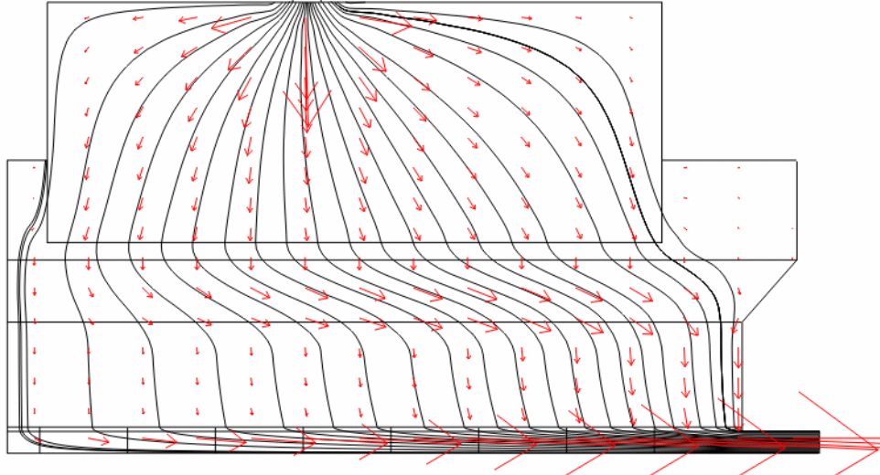
Figure 6 demonstrates the dispersion of current density in metal and cathode sections at various lengths of steel collector bars (D3, D5 and D7). The figures illustrate the effect of collector bar length on the horizontal component of the current in the metal pool. Figure 7 shows a significant improvisation of current distribution in metal and cathode even with smaller length (D5) copper inserts.
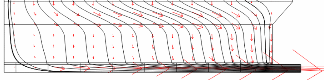
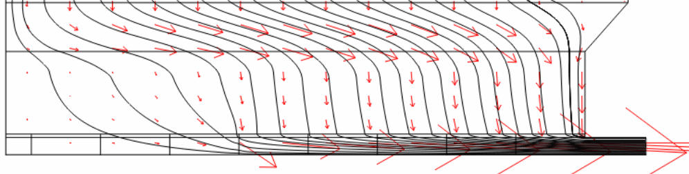
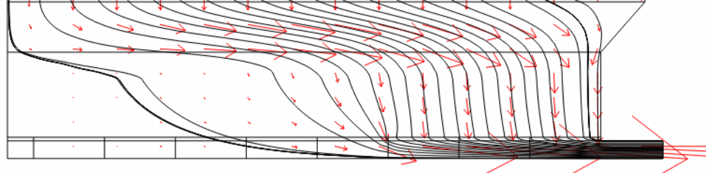
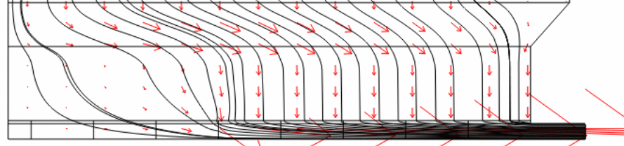
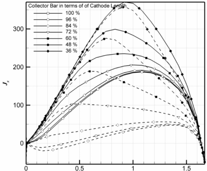
Figure 8 (a) shows the magnitude of horizontal current (jx) at two separate points, which are the mid-height of the molten metal and the surface of the cathode. Only the horizontal collector bars are used to show a comparison between copper (dashed lines) and steel (solid lines) collector bars. Horizontal current (jx) shows a variable trend. It gradually increases from the central channel to a maximum point and then decreases to a negative value near the sidewall since the current changes its direction in the side channel because of an inclined sidewall/ledge. Xiquan et al. [23] report similar current distribution in the molten metal. Lombard [22] report that the key cause of cell failure is due to the locally accelerated cathode erosion. However, it is interesting to see the impact of the copper collector bar on the current distribution. The predicted data indicate that there is a significant decrease in the magnitude of horizontal current while using copper collector bars of length more than 72% of the cathode length. Vertical current distribution is also evenly distributed (Fig. 8 b) in the metal pool with copper inserts.
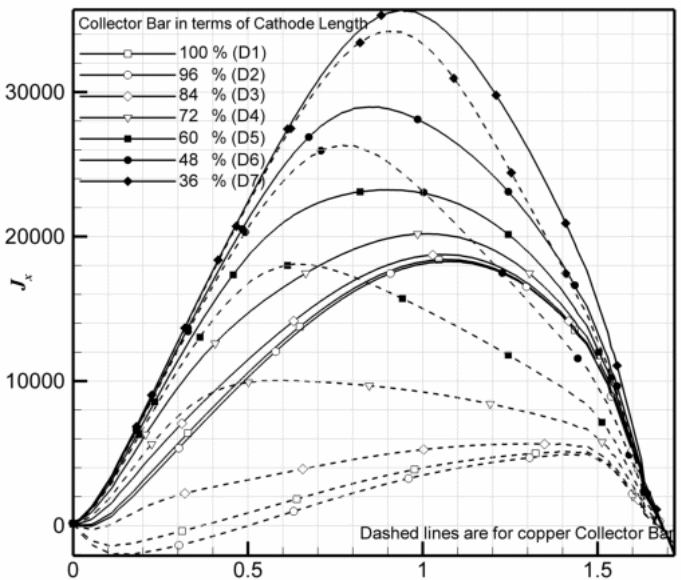
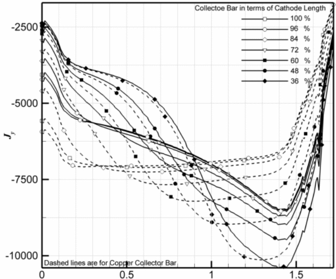
Figures 8 (c) demonstrates the horizontal dispersion of current density distribution on the surface of the cathode. It is clear that the manner of distribution resembles the distribution at the mid-height of the metal. On the whole, current density dissemination always has a peak value in all levels of the cell lining (in the metal as well as inside the cathode). However, with copper inserts (> 72% of the cathode length), these peaks are flattened considerably. These models show that the copper collector bar reduces the magnitude of the horizontal current in the molten metal, which changes the course of navigating current to vertical within the molten metal. However, the copper collector bar diminishes the amount of current density on the surface of the cathode by restructuring it over the whole surface.
Interface Tracking Methods

Fig. 6 depicts the component of forces acting on the bubble on the downward facing horizontal plate. In Fig. 6, FP is the force at the point where three phases join as a result of the pressure inside the bubble. The forces that lead to the attachment of the bubble to the surface are F1 and F2 as illustrated in equations 10 and 11.


F1 and F2 act perpendicularly in the upward direction. Therefore, the condition for disengagement of the bubble is not met when the bubble enlarges under a flawlessly horizontal surface. However, the horizontal constituent of the surface tension force may prevent the expansion of the bubble while the force arising from the internal bubble pressure increases the bottom diameter. These forces are given as F3 and F4.


The horizontal force keeps changing as the pressure inside the bubble alters with the flow injection. Fig. 4 shows that the contact angle transforms very fast during the initial formation. As θc approaches 90◦, F3 reduces as F4 increases. These alterations distort the shape of the bubble from spherical to elliptical. It is worth noting that a bubble growing below a flat plane remains stationary until the drag force brought about by the velocity of the adjacent fluid goes beyond the interfacial force [2]. The experimental observations are in agreement with those made in previous studies.
Detachment
The expansion and disengagement of bubbles have been the areas of interest of many investigations in the past decades. Three main factors determine the disengagement of an air bubble from an even surface inundated with water. These factors consist of the angle of contact, the energy on the surface of a solid and the surface tension of water. The magnitude of the area of contact between the bubble and the solid support is influenced by the angle of contact. Surface tension can be seen as a vector force towards the bubble wall on the three phase contact (TPC) line. The product of the surface tension and the contact boundary indicates the persistence of the bubble grip on the surface. Conversely, the surface energy of the surface and its coarseness influence contact angle hysteresis.
Hysteresis is the difference between advancing and receding contact angle. For instance, when a drop of water glides down a glass window, the lower region of the drop forms a larger contact angle than the top part. This phenomenon is observed when the angle is measured through the water, between the tangent to the drop wall and the glass surface. The lower section moves on the surface of the glass and is taken as the advancing contact angle. On the other hand, the upper region draws back and is taken as the receding contact angle. Similarly, when the bubble first makes contact with solid under water, it extends over the surface at the receding angle. The detachment of the bubble and the corresponding shrinkage of the contact area take place at the advancing contact angle. An equilibrium contact angle is attained when the bubble neither moves nor disengages from the surface. At this point, the mean of the advancing and receding angles is equivalent to the equilibrium contact angle. Detachment entails the reduction of the contact area as the air bubble recoils from the surface. The position of the TPC line at the advancing contact angle is a prerequisite for the instigation of the inward movement. Therefore, hysteresis and the contact angle play a vital function in the detachment process. The contact angle overshadows the contact diameter of the bubble. Subsequently, the ultimate size of the bubble prior to disengagement is a factor of the surface energy of the solid, liquid surface tension as well as the contact angle. The contact angle is always 90° during disengagement. However, the angle at detachment should be the advancing angle or slightly larger if the TPC line is moving very rapidly. The role of surface tension is thoroughly explained in experiments with oil drops on a submerged horizontal plate.
Despite numerous theoretical and experimental investigations, the mechanism of bubble formation and detachment is not clearly understood. Due to the lack of reliable information, the bubble is forced to detach when a certain criterion is satisfied. However, there is still no consistency in the definition of bubble detachment criterion. The force balance of an attached bubble as a whole is widely employed in the definition of bubble detachment criterion.
