- Introduction
- Background of Raman Amplification
- Advantages and Disadvantages of Raman Amplifiers
- Types of Raman Amplifiers: Discrete Raman Amplifiers
- Advantages and Disadvantages of Discrete Raman Amplifiers
- Distributed Raman Amplifiers
- Advantages and Disadvantages of the Distributed Raman Amplifier
- Uses of the Distributed Raman Amplifier
- Conclusion
- Works cited
Introduction
The purpose of the paper is to look at Raman amplifiers as well as their performance. Raman amplification is the process of scattering light photons from matter molecules to wave lengths that are of a higher frequency. The process is achieved when the matter molecule is excited by the light photon. The paper will also provide a comparison between the amplifiers and the Erbium Doped Fibre Amplifiers (EDFA) which need a special Erbium fibre to provide the proper amplification. The Raman amplifiers on the other hand use any type of fibre to provide amplification. The paper also covers the two types of Raman amplifiers which are the discrete and distributed amplifiers as well as cover their features, advantages and disadvantages.
Background of Raman Amplification
Raman amplifiers were discovered by Sir Chandrasekhara Raman in 1928. The Raman scattering process involved the light photon exciting the matter molecule to a higher wavelength or energy state after which the molecule is relaxed back to the normal energy state by releasing another photon as well as releasing vibrational energy. The vibrational energy makes the emitted photon to possess a lower energy state than the light photon which creates a higher wavelength. The Raman amplification process is the process where the transmission fibre provides the amplification itself by providing the fibre with pump power. A stimulated Raman scattering process is similar to the Raman Amplification process in that a photon with a higher wavelength provides a simulation of the scattering process. The initial photon released by the matter molecule is absorbed to create a higher wavelength that results in the emitting of a second photon that has a higher wavelength than the first one thereby creating amplification (Bromage 79).

The figure on the left presents the stimulated Raman scattering process while the one on the right represents the Raman amplification process. The stimulated process represents the absorption for silica fibres with energy an original energy state of 1450nm that has been amplified to a higher wavelength state of 1550nm. The Raman amplification diagram represents the gain spectrum of 100nm for Silica fibres above the pump wavelength that shows that the gain spectrum is determined by the pump wavelength (Bromage 80).
The main aspect of the gain spectrum in Silica fibres during the Raman amplification process is that the gain increases the frequency band to 40THz with a bandwidth of 6THz. The spectrum gain also creates a large peak of 13THz. The increase in frequency range is as a result of the unstructured material that is used to fuse the Silica fibres. The vibration frequencies that occur in the matter molecule stretch into frequency lengths that overlap with each other resulting in the creation of a band. The large bandwidth that is present in the Raman amplifiers along with the large saturation power of 1W makes the amplifiers a viable option to be used in fibre optic communication systems. The Raman amplifiers also have better noise properties than the stimulated scattering amplifiers with a decibel of 3dB which is considered acceptable. The amplifier was however not the recommended alternative in the initial stages of its development because it was not efficient when operated in a low energy state which in the end made its use in commercial applications to be impractical.
The Raman amplifier also faced a challenge in the form of polarization sensitivity. The amplifiers were meant to show some harmonization between the direction of the polarization power pump and the signal which were at times difficult to obtain. Polarization presented a problem to Raman amplifiers because of the high pump power characteristics that made the amplifiers to be less effective when used in communication systems. These limitations were however solved through the use of advanced optical technology such as higher Raman gain fibres and high pump power laser diodes (Bhattacharyya et al 1).
The higher Raman fibres had a low loss rate that created the adverse effect of an increase in the gain efficiency of commercial dispersion fibres. The availability of the high pump power laser diodes reduced the output power of the Raman amplifier’s to 1 Watt and below which enabled the amplifiers to be more efficient and useful in optical communication systems that have a long haul within their systems as well as channels that require high total power (Bhattacharyya et al 1).
Advantages and Disadvantages of Raman Amplifiers
Raman amplification when used in the optical regeneration process is a useful technique because of its single fibre use when compares to amplifiers that have many fibres. The gain of a particular brand is more level for the amplification process of a Raman amplifier when compared to the EDFA’s. This broad gain is useful for the Raman amplifier to so that the amplification process can be able to support more channels. The optical signal to noise ratio performance for this type of amplifier is much better than that of the EDFA with an average gain in OSNR of a 5dB. The non-dependence of the amplifiers to the meta stable states makes them most useful in states that are experiencing higher bit rates (Gumaste and Antony 98)
Raman amplifiers have difficult engineering technology that is used in their implementation design during the amplification process. Another disadvantage of this amplifier is that the effective length of any non linear effect is set by the increase of the pump power. For example a pump power of 1450nm will require a penetration into the fibre of 40 km or less. The Raman amplifier requires a high pump power level that might cause some damage to the power supply unit (Bhattacharyya et al 5).
Types of Raman Amplifiers: Discrete Raman Amplifiers
A discrete Raman amplifier is created through the use of a spool of fibre that is derived from the spectrum gain and laser pump sources that have a high sensitivity to polarization. The pump power in this type of amplifier is contained in a short length of fibre that has been specifically designed to increase the spectrum gain of the Discrete Raman amplifier. This is further explained by the figure below
The Discrete Raman Amplifiers or the DRA can be designed in a way that will see the optical communication signal being amplified to cover a frequency band length of 1300nm to 1700nm. This therefore becomes a more viable option for optical communication systems when compared to the Erbium Doped Fibre Amplifiers (EDFA) which require a special Erbium fibre to achieve the appropriate levels of amplification. The fibre has a natural limitation that prevents the EDFA to achieve amplification levels that are below 1525nm (Bhattacharyya et al 3). The DRA’s can operate in both the low-loss regions and the higher areas because they have gains of over 20dB. They are also designed to deal with the increasing number of spanning frequency wavelengths which enables them to operate successfully in a short and long wavelength (Gryspolakis et al 56).
Despite the fact that the DRA is much better when compared to the EDFA, more developments have been proposed to improve the performance of the amplifier. Developments that have been proposed include the use of small-core doped fibres made of high quality Germania that provide the amplifiers with a good saturation performance. For example, an amplifier that has been optimized will yield a net gain of 8.5dB with a bandwidth of 3dB and a total power pump of 200Megawatts. The performance of this optimized amplifier has shown that there are no saturation side effects created when the pump power exceeds the amplified signal power. The small core Germania fibre will be useful in optical communication channels that are designed with single frequencies as well as in transmission systems that require a high power output (Spirit et al 22).
Another development to the DRA is the use of Raman ring fibre oscillator (RRFO) that is counter pumped. The RRFO has been known to improve the overall optical system to a net gain of 20Db. This fibre reduces the signal power transient while increasing the net gain. This fibre is useful for the advancement of the DRA to be a future discrete optical amplifier. The development of the highly non linear fibre (HNLF) has also ensured that there is a significant increase in the net gain of the DRA when used. This reduces the high cost of using high output power (Spirit et al 89)
Advantages and Disadvantages of Discrete Raman Amplifiers
An advantage of the discrete amplifier is that it can be able to cover a large band length of 1300 to 1700nm when compared to the hand length of the EDFA which reaches a low of 1525nm. Because of this large band length, this type of amplifiers can be able to be used in areas that have a high and low loss gain. Discrete amplifiers have are more acceptable to be used when compared to the EDFA because they have provisions that allow for the gain band and also for the adjustability of gain shape in the frequency band. These amplifiers do not allow for any non linear effects to take place meaning the amplification process offers better linearity than the EDFA. A disadvantage of this type of the discrete Raman amplifier is that 1310nm band cannot be used for commercial purposes because it is unable to use the WDM in the zero scattering wavelengths of optical fibres (Islam 555).
Distributed Raman Amplifiers
Distributed Raman amplifiers are used to amplify signals throughout the various points of a network. These types of amplifiers are created by using pumps at various levels of the amplification process Distributed amplifiers can be used for both the Raman and EDFA amplifiers by incorporating the use of bidirectional pumping techniques that will create a linear gain (Gumaste and Antony 97).
These amplifiers can reduce noise generation while at the same time smoothing out the variations in signal transmissions along the communication channel. The distributed Raman amplifiers also reduce the vulnerability of the communication system or channel to non linear effects that might occur during the transmission process. The amplifiers also provide high speed transmission channels that have a large capacity to be used in long haul systems. When compared to the EDFA, they are viewed to be the better choice for amplification (Bristiel et al 16).
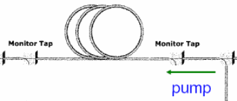
Theoretical studies have shown that the distributed Raman Amplifier can be able to achieve a higher optical signal to noise ratio (OSNR) than the discrete amplifier. The distributed Raman amplifier however achieves the same level of OSNR that is achieved by EDFA. In the amplification process, EDFA is classified as a lumped amplifier because amplification occurs in the Erbium fibre that is found in a closed amplification module. These kinds of amplifiers are placed in a span of 80 km from the transmission line. The amplification process occurs when the transmission signal that travels along the 80km span is amplified back to the original energy state at the end of the discrete or lumped amplification. This amplification is demonstrated by the diagram below that shows the distributed and lumped distribution (Islam 553).
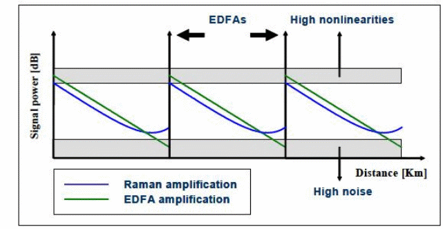
The diagram shows that while the EDFA needs a special erbium fibre to provide amplification, the Raman amplifier can use any kind of fibre to achieve amplification. The signal evolution for the distributed amplifier is represented by the blue curve. The signal is seen to be counter propagating, which is the introduction pump power at the end of each 80 km span in the transmission. The pump power is propagated continuously in the counter direction of the signal transmission. The distributed amplifier prevents the increase of the signal at a very low energy state because the gain mostly occurs along the transmission fibre (Islam 553).
The distributed Raman amplifier reduces the overall excursion that is experienced in the different levels of a signal when it goes through the transmission line. At the top level of the signal, the amplifier does not require any high level thereby reducing the non linear effects that might be experienced a high signal level. When the distributed amplifier is used at the lower level of the signal, the signal does not go down. The optical signal to noise ratio is maintained at a high level when the distributed amplifier is used in the optical communication system. If a span of 80 km is being used the distributed amplifier will give an equivalent amplification performance that spans between 35 to 38 km which makes the amplification process more economical (Islam 554).
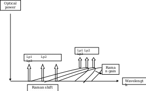
The above diagram shows the application of the distributed Raman amplification process to each repetitive section of the conventional optical transmission system. The pumping lights represented by Lp1, Lp2 and Lp3 represent the outputs of different wavelengths. The diagram shows the wavelengths of the signal and pumping lights in the distributed Raman amplification process. A wavelength of the signal and pumping lights is created within the gain band of the distributed amplifier. This wavelength should be longer or shorter than the wavelength of an optical signal light. The wavelength is set in an environment where a fluctuation in the Raman gain wavelength of the reference light is equal to the 1/5 amount of fluctuation in the Raman gain wavelength band of the signal light. This makes it possible to create a low cost distributed amplifier that can be able to gain control while at the same time compensating for Raman gains in wavelengths (Sugaya 77).
Advantages and Disadvantages of the Distributed Raman Amplifier
An advantage of using this type of amplifier is that it leads to a lower accumulation of amplified noise with the transmission line. This is as a result of the prevention of the signal power achieving a low level as occurs in the discrete, EDFA or lumped amplifiers. The distributed amplifier also allows for the cascading of gain inputs by providing a good input match. It has a good isolation frequency for the output, input amplification process. The reduction of the maximum signal power can be achieved without having to reach high amplifier noise level eliminating the occurrence of non linear effects (Islam 553).
The distributed amplifier caters for the polarization sensitivity of both passive and active devices that are in use. The configuration used in its design allows for the amplification process to incorporate other functions such as circulations, multipliers and oscillators. The amplifier provides more design alternatives for the input networks and the output transmission lengths when compared to the Raman amplifiers. The distributed amplifiers also provide a higher pump power level as a result of the currents emitted devices that have been activated. These activated devices are combined with vector techniques to the drain line of the output line (Bhattacharyya et al 3).
A major disadvantage of using this type of amplification method is that the process will require a high level of pump power. The gain of amplification will be limited because of the attenuation of the transmission band that will be exceeded by an increase in the gain of transmission channels. Any failures during the amplification process will lead to performance of the amplifier being affected adversely. Another disadvantage is that the gain during the amplification process will be limited because of the aspect of attenuation in the transmission line which will exceed the obtained gain that is as a result of the number of devices that have been activated (Islam 553).
Uses of the Distributed Raman Amplifier
The distributed amplifier is useful for under sea communication or transmission channels that are mostly used by oil rigs and excavation teams in the sea or water area. The amplifiers can also be used for locations that are separated by the ocean, sea, deserts, hills or mountains that have a transmission line that is longer than 160km. In circumstances that have a transmission link that is lower than 160 km, the EDFA can be used. One of the most important applications for the distributed amplifier is in multi span links which have spans that are longer or larger than the other links. If a ten span link is to be used that has two or three spans longer than the rest, the variable EDFA gain will be 6dB while the optical signal to noise ratio will be 5dB. The span loss considered to be normal for this type of link will be 20dB while the launch power channel will be limited to 3dBm. The distributed amplifier therefore enhances the use of the standard EDFA’s that have not undergone any modifications (Islam 553).
Conclusion
The Raman amplifiers have more advantages over the EDFA’s which makes them more appropriate to be used in optical transmission channels. The main concept behind the Raman amplifiers is the use of stimulated Raman scattering processes that are used to amplify the signals by pumping the correct wavelengths into the Silica fibres. These amplifiers are seen to be used in the Metro Network channels to compensate for the loss of transmission links during the amplification process. In future, the Raman amplifiers might eliminate the need to use EDFA.
Works cited
Bhattacharyya, Somak, Arjun Mandal, Subimal Majee and Soumo Ghosal. Popularity of Raman amplifiers in optical fiber technology. India: University of Calcutta.
Bristiel, Bruno, Shifeng, Jiang, Philippe, Gallion and Erwan Pincemin. New model of noise figure and RIN transfer in fiber Raman Amplifiers. IEEE Technology Journal, Vol. 18, No.8. 2006.
Bromage, John. Raman amplification for fiber communication systems. Journal of Lightwave Technology, Vol. 22, No.1, PP.79-83, 2004.
Gumaste, Ashwin and Tony Antony. DWDM network designs and engineering solutions. Indianapolis, US: Cisco Press. 2003. Print.
Gryspolakis, Nikolaos, Lawrence. R.Chen and Theodore Zambelis. Performance of two stage discrete fiber Raman amplifiers with and without all-optical gain clamping. Applied Optics, Vol. 44, No.1. pp 83-90. 2005.
Islam, Mohammed Noman. Raman amplifiers for telecommunications. IEEE Journal of Selected Topics in Quantum Electronics, Vol.8, No. 3. 2002.
Spirit, Done et al. Systems aspects of Raman fibre amplifiers. IEEE Proceedings, Vol.137, No.4, 1990.
Sugaya, Yasushi. Distributed Raman amplifier and WDM optical transmission system. 2010. Web.