The behaviors of stress-strain curves vary in steel owing to the degree of carbon concentration in the compound. As such, they portray ductility or brittleness. The former behavior is typical of low carbon steel materials with concentrations less than 0.25% while the later behavior is exhibited by high carbon steel materials (>0.25%).
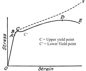
Thus, the first sample with 0.1% carbon concentration assumes a ductile stress-straintrend (Fig. 1) characterized by a well-defined yield point preceded by brief yielding and a linear stress-strain relationship (an elastic region) respectively. The yield point is defined by upper and lower yield points with the later happening when the stress decreases with material elongation. Beyond this point, the material undergoes plastic deformation significantly with increasing stress to the ‘neck’ (point ‘D’). Beyond this point there is a significant decrease in cross-sectional area with decreasing stress ultimately snapping (at ‘E’). As such, while the recorded is shown by solid line, the one which is the true stress is indicated by the dotted ones (Giancoli 13).
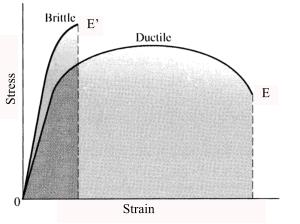
As opposed to the first sample, the second sample with 0.8% carbon exhibits a brittle stress-strain trend (Fig. 2) characterized by undefined yield point and, snaps unnoticed prior to a significant change in elongation.
Young’s Modulus of elasticity (E) = ∆ in Stress/∆ in strain
Thus, from the graphs below, ‘E’ can be obtained from the gradient of the linear sections of the graphs.
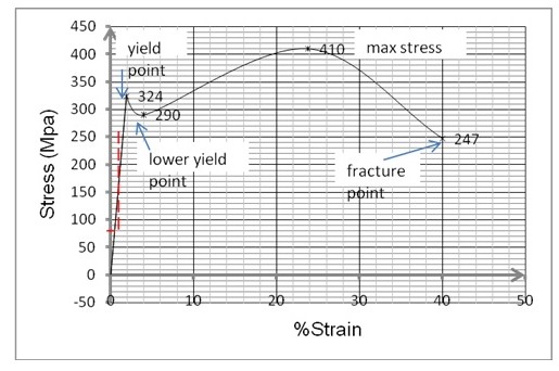
Therefore, for the low carbon steel: E = (324-0)/ (1.90/100-0)
=17.05Gpa
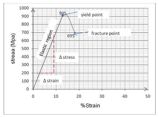
Similarly, for high carbon steel: E = (905-0)/ (12.89/100-0)
= 7.02 Gpa
Both values obtained for Young’s Modulus are way below the expected. This is so because for low carbon steel a figure of approximately 205.9 Gpais expected, while for high carbon steel a figure of 199 Gpa is expected under normal temperature conditions. The discrepancy could be owed to systemic errors or, experimental errors e.g. unstable temperature conditions. However, as expected, the former’s ‘E’ is greater than the later hence it requires a relatively greater tensile stress to fracture.
Graphs of the trends of behavior for the two samples.
Sketch and classify the fracture of sample.
Like it has been stated before, the two samples, with different carbon concentrations will portray different curve behaviors with the one with the least concentration (less than 2.5%) exhibiting a ductility behavior as opposed to brittle behavior reserved for high carbon steel (> 2.5%). Therefore, the first sample, a ductile material will exhibit the curve below (diagram 3) while the second sample, a brittle material; will trace a curve akin to diagram 4.
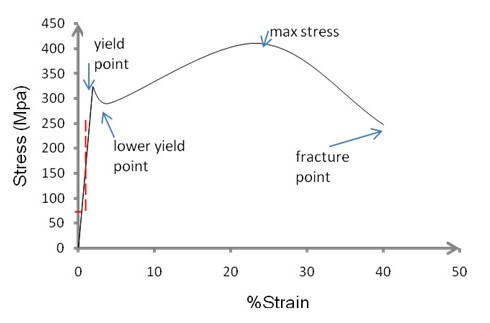
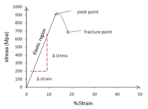
Noteworthy, beyond the yield point, ductile materials undergo plastic deformation before fracture. On the other, brittle materials fail unnoticeably prior to plasticity.
Calculate the tensile strength: percentage elongation, percentage reduction for nominal stress at fracture for each graph.
For sample 1:
- Tensile strength = maximum stress prior to ‘necking’
- =410 Mpa
The percentage elongation at fracture as portrayed by graph 1 above is 40%.
Percentage reduction for nominal stress at fracture is given by the difference between the percentage extension at ‘neck’ and at fracture/ failure. This arrives at 16.2%i.e. 40 minus 23.8.
For sample 2:
- Tensile strength= yield stress i.e. 905Mpa
- The percentage elongation before failure is 18.12%
The percentage reduction for nominal stress at fracture = % elongation at fracture-% yield extension. This gives 5.23% i.e. 18.12 minus 12.89%.
Works Cited
Giancoli, Douglas. Physics for Scientists & Engineers Third Edition. Upper Saddle River: Prentice Hall, 2000. Print.