Introduction
Before the introduction of the fly-by-wire system in civil aviation, pilots had to rely only on manual controls during flight. Fly-by-wire is an innovation that replaces an aircraft’s manual controls with an electronic interface.
Fly-by-wire is a digital flight control system that enables signals from manual controls to be converted into electrical signals after which control computers determine the appropriate response (Droste &Walker, 2003). The Airbus Company was the first airplane manufacturer to introduce this system in their A320.
The Airbus fly-by-wire system was certified in 1988 and was used the same year during the launch of the first A320 (McRuer & Graham, 1981).
Manual flight control systems are very bulky and the control cables need to be carefully laid through the relevant sections of the airplane.
The control systems and cables need redundant backup that guard against failures and as such further increases the weight of the aircraft and the work of the crew. Mechanical flight controls are prone to several dangerous issues such as spinning, stalling and pilot-induced oscillation (Pratt, 2000).
In fly-by-wire, the control of the aircraft is only achieved through the use of electrical signals. The controls are configured to control computers in the aircraft.
This means that the link between the operator and the control actuators is interposed by a computer system hence modifying the operator’s inputs with regards to the control parameters.
Fly-By-Wire
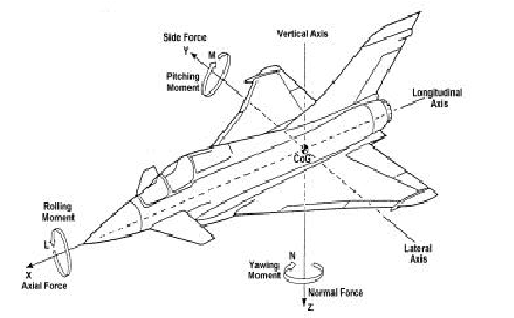
In the study of mechanics of flight, we can assume that an aircraft can be represented as a rigid body, designed by a set body of axis as shown in figure 1.
The rigid body dynamics therefore has six degrees of freedom, given by three rotations about, and three translations along the axes. This model allows modeling of all forces and moments acting on the plane (Stephens & Lewis, 1992).

Figure 1: Body axis aircraft co-ordinate system retrieved from Stephens and Lewis (1992, p.24)
In order to achieve flight control, the capability to control the forces and moments acting on the plane is imperative. If we can control the forces and moments, then by default we can control the accelerations and hence velocities, rotations and translations.
The Flight Control System is designed to achieve this through the aircraft’s flight control surfaces that include the rudder, edge flaps, trailing and foreplane (Pratt, 2000).
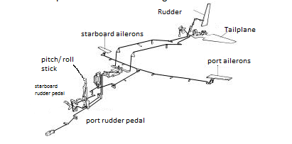
Flight control system also needs to control the thrust provided by the engines, since they also produce the forces and moments acting on the plane. On a standard airplane, control signals from the pilot are transmitted to the actuators by a system of mechanical components as shown in Figure 2.

Figure 2: Mechanical control system retrieved from Stephens & Lewis (1992, p.26)
Direct mechanical connections between the cockpit controls (rudder pedals and pitch/roll sticks) and the control surfaces that maneuver the plane were used in mechanical flight controls. In standard airplanes, computers within the plane constantly modify the pilot feel on controls while the auto-pilot computers can be able to control the actuators (Lloyd & Tye, 1992).
However in fly-by-wire airplanes, flight control surfaces are all digitally controlled and activated by means of a hydraulic system. The rudder and the Trimmable Horizontal Stabilizers in these airplanes can also be manually controlled. The early mechanical means of control had very high levels of integrity, in terms of the probability of the loss of aircraft control.
In FBW planes, the side sticks are used to control the plane in pitch and roll as well as indirect control through turn coordination in yaw (Gibson, 1999). The flight control computers in the planes interpret the pilot’s inputs and consequently move the surfaces as required to accomplish the desired flight path.
When the plane is in auto-pilot mode, the flight control computers receive flight signals from the auto-pilot computers. Flight control computers in FBW planes not only control operations but they also monitor them.
The response of the aircraft to signals is feedback to both the flight control and auto-pilot computers through specific sensors and then sent for display to the aircraft crew through dedicated screens (Gibson, 1999).
In order to ensure that the high integrity levels of earlier mechanical systems are achieved in FBW planes, numerous lanes of computing and multiple signal sources are required to offer redundancy.
These systems also need to be cross-monitored in order to ensure that failed equipments are identified and isolated thus ensuring safe operation. A broad built-in-test system is also installed, to guarantee that the system is working in the expected capacity and is safe to fly before each flight and also to identify and isolate failures before flight (Lloyd & Tye, 1992).
Basic Operation
Although fly-by-wire systems are relatively complex, their operation is relatively simple to understand. When the side-stick is moved by the pilot, a signal is sent through multiple channels to a computer. In most situations, a Triplex is used i.e. the signals are sent through three channels.
Once the computer receives the signal, it adds the voltages of the signals and divides this with the number of signals received to achieve the mean average voltage (North, 2000). After this, the computer adds another channel and the signals are relayed to an actuator connected to the control surface thus causing the surface to move.
A negative voltage is then sent by potentiometers in the actuator back to the computer describing the location of the actuator. When the desired position is achieved, the incoming signal and feedback cancel each other out causing the actuator to stop moving (Moir, Seabridge & Jukes, 2003).
The fly-by-wire technology enables the aircraft computers to function without any input from the pilots. The fly-by-wire control systems have enabled automatic stability system to be included in the plane and act autonomously to the pilot’s input.
To enable automatic stabilizing systems to operate, gyroscopes that have built-in sensors are installed in the aircraft to sense movement changes in yaw, roll and pitch axes (Moir, Seabridge & Jukes, 2003). Any movement that deviates from the flight level axis triggers a signal to the computer that responds by moving the actuators thereby causing automatic stabilization.
Benefits and concerns of the Fly-by-Wire technology
The main advantage of fly-by-wire is the ability to mold the system’s attributes at all points in the plane’s flight envelope. Flight envelope protection is achieved through the use of flight control laws which are scheduled according to the flight conditions.
Another benefit is carefree handling that is achieved in two ways. The first way in the provision of carefree handling is through providing controls for the angle of attack and the suppression of the angle of sideslip thereby preventing the plane from stalling.
The second way of achieving carefree handling is by using automatic controls to limit the roll rate and normal acceleration in order to avoid over-stressing of the airframe. Carefree handling is mainly a mean to reduce the workload of the pilot especially during maneuvering in order to avoid wind shears and obstacles (Moir, Seabridge & Jukes, 2003).
The fly-by-wire technology also provides aircraft agility. This helps in providing a mean for quick changes in velocity vector and fuselage aiming.
The technology also allows the control of an unstable airframe through improved lift/drag ratio and an enhancement in the maximum lift capacity that contribute to increased aircraft turning capability. Apart from this, the technology also reduces drag through optimized trim setting of the controls.
Fly-by-wire technology has also enabled reconfiguration to allow flight continuation or safe recovery following system failure (David, 2000). Advanced autopilot system has also reduced the pilot’s workload during flights.
Finally, fly-by-wire technology has led to reduced maintenance cost due to the decrease in mechanical complexity and also the advantages arising from the built-in tests. These benefits can however only be attained if appropriate control law architecture is established.
Control laws can only be established if there is a good knowledge of the systems, safety measures and equipment engineering, flight control and flight dynamics (Lloyd & Tye, 1992). Although the cost of setting up the fly-by-wire technology is relatively high, the performance and safety benefits easily justify this cost.
The main concern posed by this system is reliability. Mechanical control systems only fail gradually thus allowing engineers and the crew to identify and fix these systems according. However, the chance that all computers in an airplane may fail could lead to the total lack of control of the plane.
Modern fly-by-wire airplanes have introduced redundant computers and mechanical flight control back-up in order to reduce the chances of overall failure. Built-in tests and independent fly-by-wire channels have also been introduced to ensure that in no time can all the systems in the plane fail.
Conclusion
In civil aviation, no invention has had a greater impact that the fly-by-wheel technology. This technology was first experimented for military operations but it was however introduced in civil aviation by the Airbus Company in their A320 plane.
The fly-by-wheel technology has offered several benefits to civil aviation that would otherwise been not achieved. One of the main advantages is that fly-by-wheel control systems have enabled integration of auto-stabilization system and flight envelope protection.
The fly-by-wheel technology has been revolutionary in the civil aviation field as it was the starting point for various innovations that have been realized over the years. Further developments that have arisen due to this technology include fly by optics, power-by-wire, intelligent flight control systems, and fly-by-wireless systems. These systems have all enhanced the efficiency of aircrafts by reducing weight, improving maintenance and crew workload as well as enhancing safety.
In the past, aircraft manufacturers had to rely on extensive connections between the cockpit and the control surfaces requiring the need for joints, pulleys and long cables. This not only increased the weight of the aircraft but also increased the workload of the crew as well as posing the risk that some defects may pass unnoticed.
The fly-by-wire system has negated all these concerns and has provided a mean to ensure that civil aviation is safe, effective and cheap. Considering all the advantages brought by this system and the potential for future developments, fly-by-wire systems is definitely one of the most important developments brought into the civil aviation field thanks to Airbus.
References
Droste, C., & Walker, J., 2003. The General Dynamics Case Study on the F-16 Fly-By-Wire Flight Control System. Reston, VA: AIAA Professional Study Series.
Gibson, J., 1999. Development of a methodology for excellence in handling qualities design for Fly by wire aircraft. Delft, NZ: Delft University Press.
Lloyd E., & Tye W. 1982. Systematic Safety (Safety Assessment of Aircraft Systems. Civil Aviation Authority, London, 1982.
McRuer D., & Graham D., 1981. Eighty Years of Flight Control: Triumphs and Pitfalls of the Systems Approach. AIAA Journal of Guidance and Control, 4(4), 64-88.
Pratt R. W., 2000. Flight Control Systems Practical Issues in Design and Application. IEE Control Engineering Series, 57 (1): 220-258.
Stevens B. L., & Lewis F. L., 1992. Aircraft Control and Simulation. New York: John Wiley & Son, 1992.