Introduction
This paper provides a detailed network design and layout implementation for the newly acquired university administrative offices, lecture rooms, library, and computer labs. It will consist of an IP addressing scheme to provide each node and network segment unique identifiers having the network hosts linked with appropriate media. The design will consist of physical and logical topologies with security implemented to provide perimeter defenses.
Physical and Logical Network Design
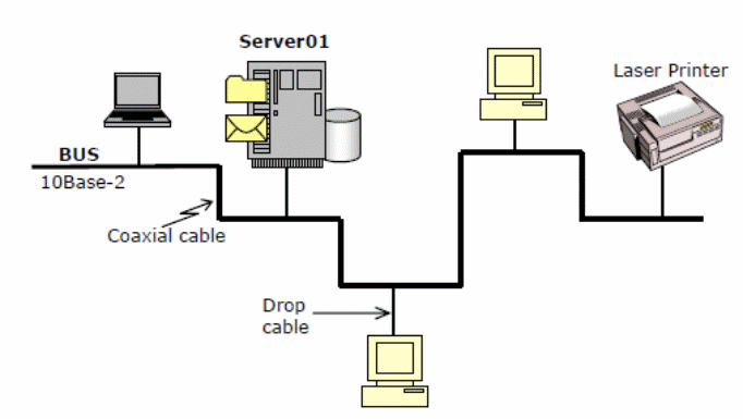
The network is defined by a physical topology with a physical layout of interconnected nodes using the bus as a backbone topology. The internal network is connected to the external network with a T-1 link from Verizon (ISP) using a dynamic NAT router installed and tested and overloaded with PAT to support a higher number of clients with one public IP address, from the single class B IP of 191.1.15.1. All subnet hosts will be based on TCP/IP with an IP address of 10.15.0.0.
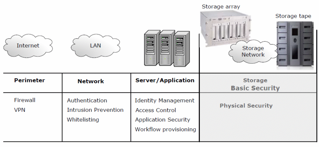
The benefits include cost savings, cabling, and ease of implementation with a section of the physical topology shown in figure 1 below. The network defense will be multilayered as in figure 2 below. A hybrid topology consisting of the star at the offices will allow for incremental node growth and avoidance of failure, and easy troubleshooting. The ring topologies with workgroup nodes provide the logical connections of all the network hosts.
The ISP provides internet services via the NAT router connected to the five switches linking each of the subnets for each server. Dedicated servers as mentioned earlier to optimize performance are used.

The ring topology will be used at the computer lab because it is easy to troubleshoot, and provides simple cable layering, and connects students’ computers directly.


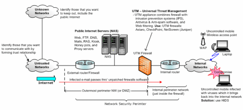
Figure 4 consists of the routers configured with a Yvette firewall with servers and the wireless portion. There could be an external router, servers in the outer perimeter to provide IT services, the UTM firewall that separates the internal network from the external network, with the workgroups located within the internal perimeter with the wireless network. To keep the confidentiality, integrity, and availability of data/information, physical, logical, and technical controls that access control lists, rules, and policies when well implemented will provide additional security. Authentication will be required to access data with an access control list defined for each user and for the administration; there will be a need to use digital signatures, and keys to access sensitive information.

The cabling for all hosts in the network will be Cat 5 twisted pair with a T-1 demarcation provided by the ISP, which provides connection speeds of 1.54 Mbps with a provisioned support of 100 to1000 megabits Ethernet. The media provides the flexibility to upgrade to fiber-optic cables which provide higher data rates. Cat 5 enables the transmission of data without the cross talk problem. The Cat 5 cable can provide data transmission over the 240 feet range, which does not exceed the 300 ft required to install a repeater.
Networking Devices
A switch will be used to provide interconnection with the upper layer of the building through the ceiling to avoid attenuation in addition to being cheap, easy to extend, and allows easy addition of nodes. The switch enables avoidance of collisions and avoids loopback logic through the NIC. Other networking devices will include the WAP for wireless connections to the central network, internal router for routing, firewall with filtering rules on the TCP, UDP, and the bastion host to ensure secure communication.
Additional Network devices
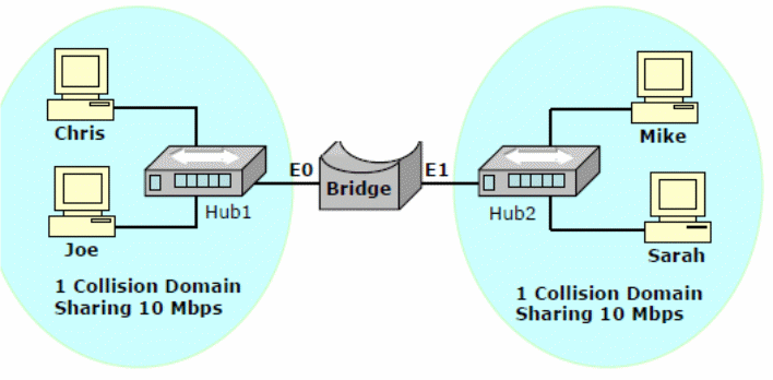
Each node will integrate a NIC (network interface card) into the serial expansion slots with unique IP addresses to interface with the network on a collision domain. A hub will provide multiple connections with the subnets via the switches; a router will connect internal and external subnets, Broadband modem to connect with the internet. Other devices include printers.
Physical layout
Typical sections are shown in figure 5 below.

Both sections of the lab and other sub-networks of the workgroup computers will be connected with a switch through the hubs
Network Addressing
The address is shown below.
Public router address: 191.1.15.1
Network Address: 10.15.0.0
Justification
Because of the mentioned benefits, the size and low costs to acquire the devices and implement the network underpinned the type of network adopted.
Summary
This paper provided a detailed view of the design and implementation of a secure network connection with the hostile internet, using a layered network defense mechanism. It implements the network using Cat 5 twisted pair cable, with external and internal routers, hubs, and switches to provide the logical design. The design provides flexibility for incremental growth or redesign.