Entity Relationship Diagram for Riyadh Metro Database
Preferably, entity-relationship diagrams illustrate the logical organizations of databases (DB). According to Wei and Link (2019), no particular database design structure can be rated more efficient than the other. While other storage structures are purely constructed for performance optimization, others are tailored specifically for the storage of huge data volumes. Essentially, entity relationship diagrams are based on two fundamental concepts, namely, entities and relationships (Silberschatz et al., 2011). An entity refers to the individual tables that constitute a database. Moreover, relationships define the association between the attributes in the tables, or the individual records stored in a DB.
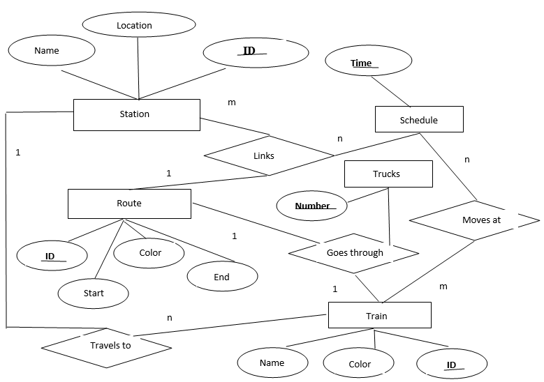
While some developers prefer flowcharts in the design of databases, Entity Relationship Diagrams (ERDs) tend to be discrete and easily understood, even by novice audiences. Figure 1 below is a prototype version for Riyadh Metro. It provides a rough overview of all the tables included in the system design, alongside their attributes that define the relationships that exist in the database. The ERD below shows the different types of relationships that occur within the system design. For instance, throughout the design of the automated Riyadh Metro system, the stations’ table has a many-to-many relationship with the schedules table.
Similarly, trains have a one-to-one relationship with the available service routes. Additionally, the stations table has a one-to-many relationship with the trains table that has a many-to-many relationship with the different schedules available for travel. This means that a particular station can have many schedules with different trains and trucks available for selection at one particular time. However, the trucks and trains are specific to a single route.


Relational Schema for Eliminating Redundancies and Identifying the Keys
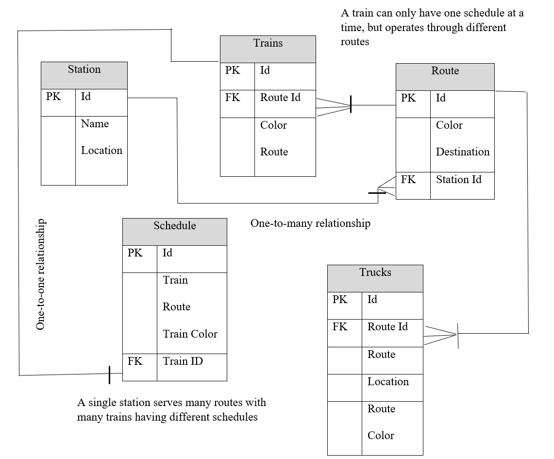
A relational schema refers to the set of attributes that describe the logical organization of individual tables in a database. In more enhanced DB designs, the relations are structured to include the data types for each table record (Wei & Link, 2019), However, the above-drawn prototype (As shown in figure 2) has been organized to be discrete for easy understanding. The prototype constitutes five tables and is arranged so that when a traveler books a train or a truck for travel, the process is initiated from the station table. Here, the clients select their desired destination, their preferred train or bus alongside their specific routes before submitting their requests for processing.
Moreover, all the attributes with foreign keys have referential integrity, ensuring that the values of the primary keys match in both the parent and child tables. In addition, Reverse Integration (RI) safeguards correspondence between database entities, providing that only accurate entries are stored in an automated system.
The table designs in the relational schema consist of primary keys to prevent redundant entries in the database. By definition, such keys are used to enforce uniqueness so that the design is not full of redundant entries, which can potentially slow down the speeds of access. Similarly, the schema denoted the various foreign keys implemented in the design to create relationships between the tables. According to the description, foreign keys are primary keys in different tables used as attributes on different tables. Therefore, the main objective of the relational schema is to deliver a declarative process for identifying data and queries.
References
Silberschatz, A., Korth, H. F., & Sudarshan, S. (2011). Database system concepts (6th ed.). McGraw-Hill Companies, Inc.
Wei, Z., & Link, S. (2019). Embedded functional dependencies and data-completeness tailored database design. Proceedings of the VLDB Endowment, 12(11), 1458-1470. Web.