Introduction
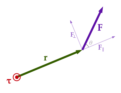
If the action of all forces applied to the body is compensated, then the body is said to be in a state of equilibrium. However, a solid body may continue to rotate about its axis even if the sum of all forces is zero. In this situation, a torsional momentum occurs, which has a vector calculus, as shown in equation (1). Thus, the direction of the torque with respect to the point is essential and shows the ability of the body to rotate in the direction of the resultant vector. The scalar value of this torque is determined through the sine of the angle, as shown in equation (2).


Objectives
- Determine the torque for a solid.
- Graphically visualize the dependence of force on angle.
Materials
- Force Scale.
- Hanger.
- Protractor.
- Ruler.
- Weights.
Preliminary setup and questions
This experiment uses different masses as tools to test the torque theory. For each of the symbols used, the following is a terminology description:
- F – physical force.
- r→ – radial vector.
- r – the modulus of the vector, or its length.
- θ – angle in degrees between the radial vector and the resultant force.
Procedure
The entire experiment was conventionally divided into two parts. In the first one, equilibrium was studied for the setup used. In the second part, dependences for torque as a function of radial vector and force were determined.
- The procedure of the first part. The first weight of a given mass is suspended from the rig, with the holder tilted toward the placement of the weight. The equilibrium condition is reached by selecting the second weight of the necessary mass. The holder, in this case, is characterized by the torque, which is calculated through the levers of force.
- The procedure of the second part. For the second part of the experiment, the torque produced by one weight in the vertical position is evaluated. For this purpose, the values of forces, lever length, and torque for the first load and the distance and angle value for the second load are recorded for the retracted state (springs are used). Based on the results of all measurements, a data table is created, and calculations are made.
Data tables
Table 1. Torque measurements for different weights.
Table 2. Measurements of the second force as a function of theta angle.
Analisys

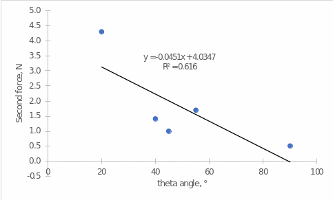
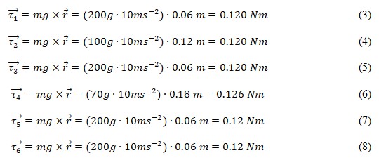
Analysis of the graphical results shown in Figure 2 shows that there is a moderate linear correlation between the theta angle and the second force, which means that we can say that, in general, when the degree value between the radial vector and the force vector increases, there is a decrease in the second force by 0.05 units. Additional results can be found for the first part of the experiment, which evaluated the relationship between distance and mass suspended on the holder for each of the three attempts. For the first attempt, equations (3) and (4) show r calculations. Similar calculations are given for the second and third attempts, respectively.

It is well visible that the torques for each of the tests are generally similar, which means that the masses and distances were chosen so as to achieve an equilibrium rotation of the body each time.
Conclusion
In the current experiment, it has been shown that using theoretical calculations of torque through the mass of the suspended weight and distance is of applied value. In other words, it is possible to use different masses and distances of the arm to determine torque. In the present work, these variables have been appropriately manipulated in order to determine the equilibrium rotation of a solid. In other words, the torque r was identical in five of the six attempts. In addition, it was shown that an almost linear relationship was found between the angle between the radial vector and the resultant force and the second force.
Reference
Jones, A. Z. (2018). Calculating torque. ThoughtCo.