Water Supply History
Inhabitants of Woburn, just like those in other small town in Massachusetts, depended on local springs and household wells for water supply. Supply of water to the community of Woburn has historically been marred by poor quality and insufficient supply. This dates back to the time when an attempt to construct a centralized water system during the early 1870s was made. This system involved pumping of water from an excavated filter gallery from Horn Pond’s side of the pond (Tarr 5). Massachusetts State Board of Health (MSBH) alleged that the water from Horn Pond was contaminated with manufacturing wastes in 1895. However, the water which came from the filter gallery was safe for consumption.
In 1903, the water from the filter gallery became increasingly impure due to contamination with high level of ammonia and iron. As such, MSBH suggested that an alternative water source be looked for. Quabbin Reservoir which was run by the Metropolitan Water District was cited as one of the viable alternative water sources. A new well was constructed in 1908, located at the south of the filter gallery (Tarr 20). Following the 1923 drought summer, the city drew unhygienic water direct from the Horn Pond. As a result, MSBH advised the citizens to boil water before use. Although it resulted in taste problems, a chlorinator was installed during the same year. In 1920s, high demand for water forced Woburn to construct several additional wells around the west and south sides of the city.
During the subsequent 20years, “problems with the taste, odor, and supply of water from the city wells continued to arise” (Tarr 23). Whitman & Howard was contracted by the city in 1955, to study and recommend ways of improving the water system. The Whitman & Howard submitted their report in 1958, suggesting that several wells that supplied water to the public were overly polluted. They recommended that further areas near Mishawum Pond should be explored. Consequently, more wells were made, though this was not the end of problems as the citizens kept complaining of water impurities form some specific wells.
Today, Woburn supplies water to millions of users. Two-thirds of its water is sourced from the municipal wells A-F, which are adjacent to Horn Pond. Quabbin Reservoir in central Massachusetts is the source of the remaining two-thirds (this is as a result of an accord with the Massachusetts Water Resource Authority).
Daily water usage
Woburn residents consume approximately 26 million gallons of water every day (Tarr 25). In average, a single resident consumes between 80 and 100 gallons of water daily. As the population of this community continues to surge, water resources are expected to be used at an increased rate.
How the water is treated
The treatment is usually done in stages. The treatment processes should have proper residual waste management; incur minimal wastage of source water, and utilize adequate energy for treatment. The plant should not cause grave environmental problems. Tarr notes that water utilities consume about 3% of the total electricity produced in the US (12). This is generally used for pumping the water. Treatment plant applies a mixture of filtration, disinfection, sedimentation, coagulation to ensure that the public consumes clean and safe water. The following process is followed during the conventional water treatment:
Prefiltration
Water prefiltration is used to reduce the amount of suspended solids. Prefiltration utilizes coarse sand or gravel. The types of prefilters that are used are vertical prefilters, which are more popular, horizontal prefilters and pressure filters, which makes use of pressure in removing suspended solids. Prefilters are vigorous, do not need chemicals and their parts are regulated which makes them very advantageous. However, “they not only require regular cleaning and maintenance, but also are ineffective removers of fine particles such as silt and clay particles” (Tarr 21). Prefiltration does not remove viruses and bacteria that are linked to fine particles.
Sedimentation
The particles that move around the pool at a slow speed are usually suspended through a process known as sedimentation. A grit chamber helps to remove big and grained solids through a simple sedimentation process. In this chamber, the slow moving water passes by while at the same time, the solids are suspended and felled. However, this process does not remove small particles as the water moves at relatively high speed hence limited time for suspension.
Coagulation
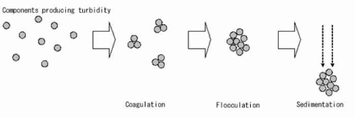
To remove the fine particles, chemicals such as polymers, salts and aluminum are included in the water. Some examples of these coagulants are aluminum sulphate, ferric chloride, ferric sulphate or polyelectrolytes. After occurrence of this neutralization reaction, the particles coagulate in a process known as flocculation. The large particles which are called floc, become heavy and promptly sink to the bottom of the water tank through sedimentation. The sedimenter’s outlet, located near the top of the tank, makes it possible to remove water by a surface channel.
How the system is pressurized to deliver water
Booster pumps are used to energize the water system. As the water flows down the system, total dynamic head is reduced, and bumps into increased gradient as distinctive demands pumps out energy. If the supply is sufficient, “booster pumps can be placed to energize the system some distance from the source.” (Tarr 26). The booster pumps are usually triggered by pressure switches. When the pressures reduce below the normal, the system triggers the pump to act and energize the system. The pump disengages the moment the normal dynamic pressure is restored. To provide more reliable pressure, elevated tanks are used. For example, “an elevated tank provides supply to strategic zones in large systems or an entire supply for a smaller community” (Tarr 29).
Type of piping used, standards used in installation
Polyvinylchloride (PVC) is the pipe used under this system, though it maybe alternated with DIP. The standard of PVC that is used in this system is produced by “an extraction procedure that elongates the grain of the material matrix” (Tarr 25). PVC has a high capability of resisting bacteriological deterioration. Nonetheless, this material is “sensitive to prolonged light exposure and should be stored appropriately” (Tarr 26).
Any construction and installation in regard to this water system “shall be in accordance with the City of Woburn Utility Construction Specifications.” (Tarr 26). In addition, all construction shall adhere to the relevant codes and regulation comprising but not limited to, “DEP regulations, MWRA regulations and Title V” (Tarr 27). Any person or entity that disregards these standards will be subjected to a stern fine.
Type of hydrants, placement, number
Woburn’s Municipal Water Supply System uses different types of hydrants to perform its critical services. “Familiarity with the operating procedures and nomenclature of each type is vital to efficient and effective fire ground operations.” ( Tarr 29).
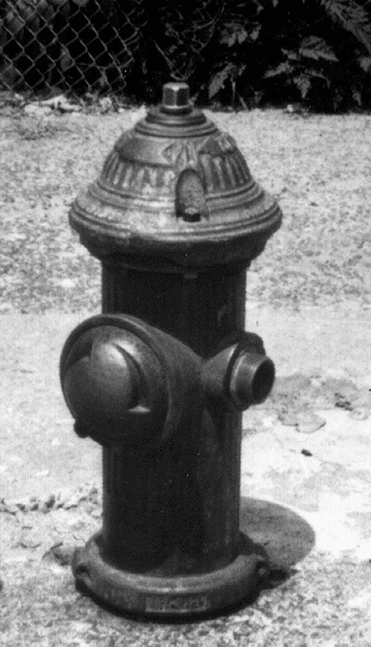
Smith Low Pressure Hydrant – This hydrant has a silver bonnet and is black in color. It has two outlets, one 4 1/2 inch and one 2 1/2 inch. It has two valves; a drain and a main which relies of operating nut for activation (see Fig. 6-1).
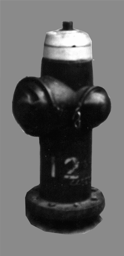
Dresser Low Pressure Hydrant – This one differs from smith in appearance though they function in a similar manner. The bonnet is silver and the barrel is painted black. It contains two outlets, that is, one 4 ½ and one 2 1/2 inch. The valves include the drain and the main. The operating nut is the activator in this case (see Fig. 6-2).
Chapman and Eddy Hydrants – this type differs from both smith and Dresser hydrants. “These hydrants will have either two 2 1/2 inch outlets or one 2 1/2 inch and one 4 1/2 inch outlet” (Tarr 29). This hydrant closes and opens in an opposite direction to that of Smith and Dresser. The layout of the pipes is as shown on fig 6-3.
Works Cited
Tarr, Macdonald. Tarr’s [sic] and related famalies [sic]. New York: F.M. Tarr, 1987. Print.
Copies of hydrant testing data from ISO reports Woburn
Massachusetts Peter J. Murphy, Ph.D. Consultant
- Figure 1: 1964-1969 Pipe network with pipe numbers and diameters Figure 2: 1970-1979 Pipe network with pipe numbers and diameters Figure 3: 1984 User Demand Areas
- Figure 4: 1964-1969 User Demand Areas by Geocodes Figure 5: 1970-1979 User Demand Areas by Geocodes Figure 6: San Jose Fluoride Prediction- PPM
- Figure 7: San Jose Fluoride Measurements- PPM Figure 8: Woburn Fluoride Re-prediction- PPM Figure 9: Woburn Fluoride Measurements- PPM
- Figure 10: Typical Exposure Area of 1964-69: June, 1966
- Figure 11: Large Exposure Area of 1964-69; October, 1969
- Figure 12: Small Exposure Area of 1964-69: June, 1969
- Figure 13: Typical Exposure Area of 1970-79: March, 1979
- Figure 14: Large Exposure Area of 1970-79: October, 1974
- Figure 15: Small Exposure Area of 1970-79: October, 1976
- Table 3: 1964-1969 User Demand Areas by Geocodes
- Table 4: 1970-1979 User Demand Areas by Geocodes
- Table 5: Well Use and Pumping Rates and Total User Demand
- Table 7: Great Oaks Flouride Validation Results Table 8: Woburn Fluoride Validation Results Table 9: Monthly Averaging Process
- Table 10: 1964-1969 Exposure Index
- Table 11: 1970-1979 Exposure Index
- Table 12: 1964-1969 Cumulative Exposure Index
- Table 13: 1970-1979 Cumulative Exposure Index
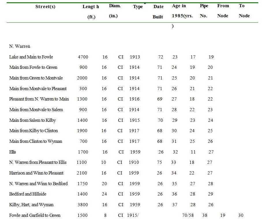
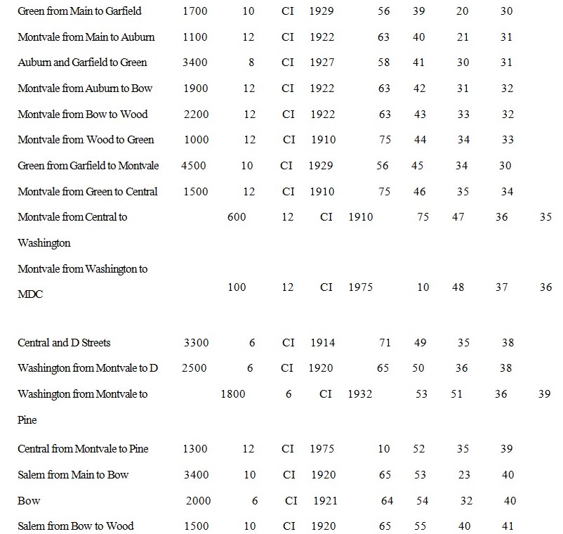
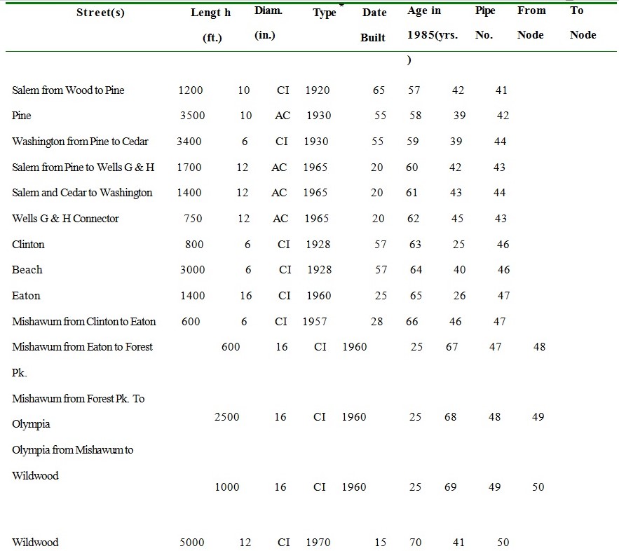
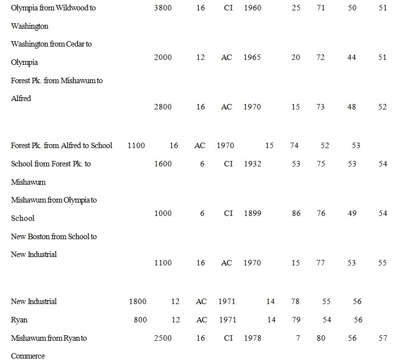
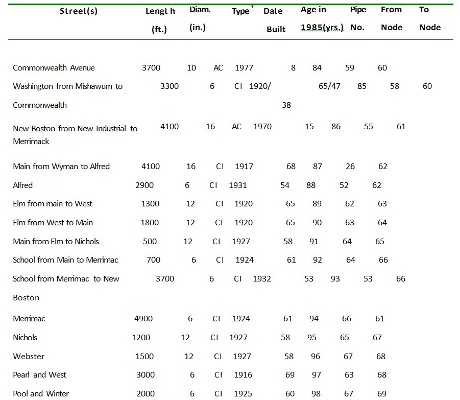
Table 1
1985 Principal Water Pipes in Woburn, Massachusetts
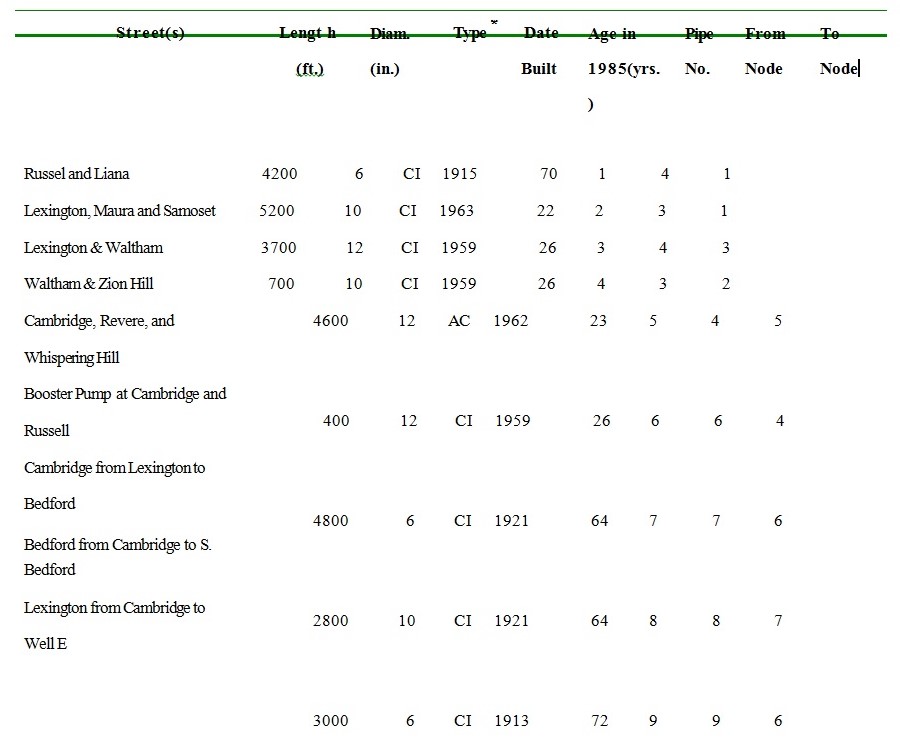
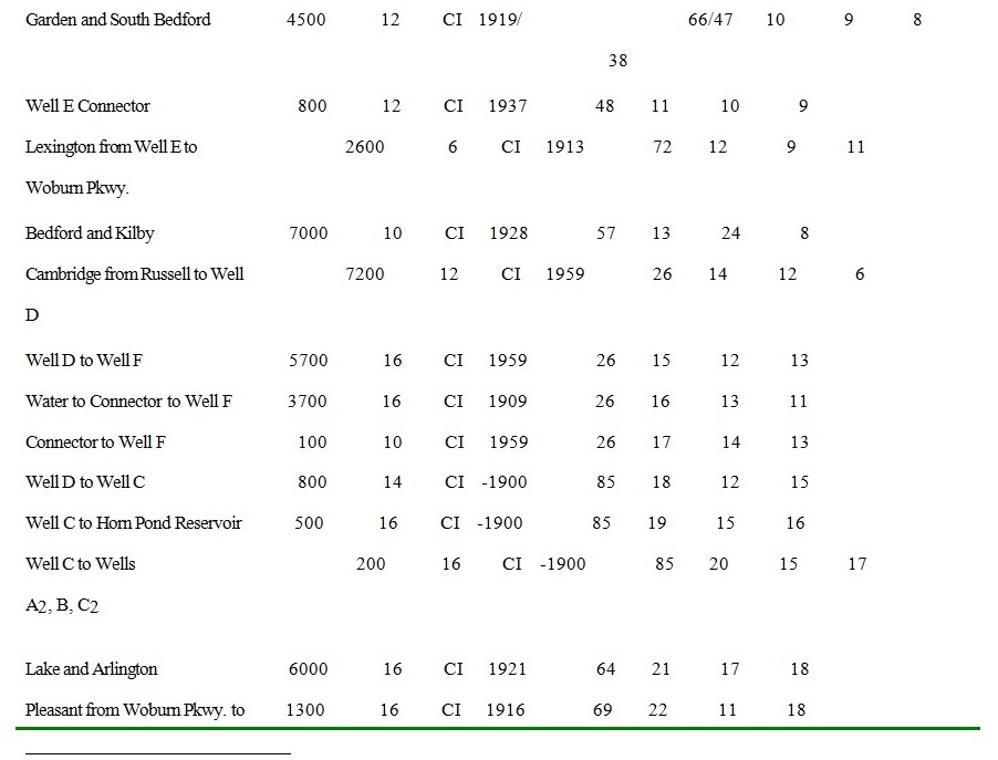
* CI = Cast Iron
AC = Asbestos Cement
