The Shard is currently the tallest building in the United Kingdom with very unique features based on the modern architecture. The use of Building Information Modelling was critical in ensuring that the project was conducted as per the specific needs of the clients and government. The system goes beyond the 3D model popularly used in the past to design structures. It also helps in ensuring that the project met time and cost specifications. Its usage ensured that the Shard project was a success.
Background of the Building Project
The Shard is a 95-storey building in Southwark, London and is currently the tallest building in the United Kingdom (Gohn 2009). Forming part of London Bridge Quarter development, the idea of this building emerged following a White Paper that was issued by the United Kingdom’s government that encouraged development of tall buildings in strategic transport hubs (Ecton 2012). Soon after the White Paper, Irvine Sellar and his partners came up with the idea of redeveloping Southwark Tower based on modern-day architecture. They wanted to come up with a unique structure that would not only change the skyline of the city of London but also introduce a new era in the country in terms of building designs. In the spring of 2000, Sellar travelled to Berlin, Germany to meet Renzo Piano, a renowned Italian architect to help in designing the building. In his mind, Sellar had a clear image of what he desired in terms of the design and height, but he needed an expert who could understand his idea and translate it into a functional plan. Renzo came up with the initial design that Sellar then presented to the government for approval. However, the Commission for Architecture and the Built Environment, Royal Foundation, and English Heritage opposed the plan saying that it was not in line with the heritage of the city. The opposition complicated the design work even further. The architect not only had to come up with a unique tall modern-looking structure as demanded for by the client, but had to introduce some aspects of English heritage in it to get the approval needed for the implementation.
It was at this stage that Building Information Modelling became very relevant in the design of the Shard. Instead of coming up with a design in a piece of paper as used to be the case before, the architect had to develop a digital representation of the physical and functional characteristics of the planned building (Gohn 2009). The digital representation of the building clearly gave an image of proposed completed building, showing both the exterior and interior parts of the facility. The model was meant to help a number of stakeholders who had interest in the facility. To the clients, the digital representation helped in showing all the physical structures and its functional characteristics so that they could know what to expect. For the government agencies, they would have a real image of the completed building and how it would blend with the immediate environment and change the skyline of London. Other professionals such as engineers, quantity surveyors, among others also needed this digital representation to determine the actual cost of the project and to know how to implement the plan more effectively. The figure below shows the plan that was finally approved by the government under the office of the Deputy Prime Minister.

After the approval, the next important phase was to source for funds for the project. In September 2006, Sellar and his partners were able to secure funding of £196 million from Nationwide Building Society to initiate the project. 12 months later, demolition of Southwark Towers was initiated to pave way for the planned ultra-modern structure. In November 2007, the contract for the construction of Shard was awarded to Mace at a fixed cost of £350 million. The demolition of Southwark Towers was completed in early 2009, when United Kingdom and the world at large were deep into the recession. The cost of the construction increased to £435 million because of inflation and other economic forces that the country was going through. As the cost increased, the developers had to get additional funds from other interested investors. Qatar National Bank, Qatari Islamic Bank, Barwa Real Estate, and QInvest both joined Sellar Property to invest in this project (Pica 2015). Construction work begun on March 2009. By March 2012, the structure had been completed and the project manager and his team started the process of preparing it for inauguration. The building was finally inaugurated on July 5, 2012 in a ceremony presided over by Hamad bin Jassim bin Jaber Al Thani who was then the Prime Minister of Qatar, and Price Andrew, the Duke of York (Pica 2015). The figure below shows the Shard on the night of inauguration.


Comparing figure 1 and figure 3 above, it is clear that what was proposed at the concept development stage with the help of BIM system is what was finally delivered when the project was completed and finally handed over to the owners. According to Littlefield (2012), the Shard project is a clear demonstration of the power of BIM system. The system makes it possible for the project owners to have a virtual form of the completed facility in its functionality form so that if there are adjustments which are needed, they can be introduced at the planning stage before the actual construction can begin. The owners will know exactly what to expect even if they do not directly supervise the project.
Mission of the BIM System for the Shard Project
According to Banihashemi (2012), Building Information Modelling (BIM) refers to a digitised representation of all the physical and functional characteristics of a given facility. Littlefield (2012, p. 44) says that BIM is “a shared knowledge resource for information about a facility forming a reliable basis for decisions during its life-cycle; defined as existing from earliest conception to demolition.” BIM system goes beyond the 3D model when developing a plan for a structure. It also details time which is its fourth dimension and cost as its fifth dimension (Banihashemi 2012). The figure below gives a diagrammatic representation of what BIM system for a building project entails.
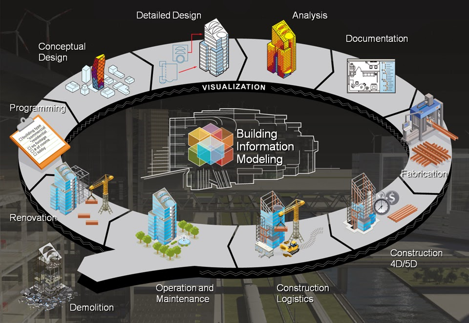
To understand the mission of BIM system for the project under analysis, it is important to understand the stages involved in this system. As shown in the figure above, everything starts at the programming stage where the project owner comes up with the idea and shares it with an architect. The architect is expected to come up with a conceptual design of what the client expects. The next step is to develop a detailed design based on the recommendation of the customer. It is at this stage that the architect is expected to integrate beauty, regulatory requirement, and functionality of the structure. The next step is the analysis where the client, the architect, and other experts share knowledge about the project, primarily focusing on the cost and time needed for the project. The information is then documented as shown in the figure above. The next stage is the fabrication, where a digital model is once again developed based on the agreed conditions (materials, shape, size, and functionality among other factors). The next stage is the construction. It is at this stage where the 4D and 5D (time and cost) of the project must be kept as per the plan. The next phase is the construction logistics where the materials and structures are assembled and the actual structure put up as per the plan. The next stage is the operations and maintenance where the building is put into actual use by the owners. The final stage is demolition as per the plan. It is often stated how long the structure should last before it is finally brought down after its lifespan. It is, therefore, clear that the mission of BIM is to come up with a plan that will facilitate sharing of information among professionals when developing a building in order to inform the owners and approving authorities what the finished project will look like, including its functionality, within a given setting.
Comparing BIM Software Available To Every Professional Discipline in the Building Project
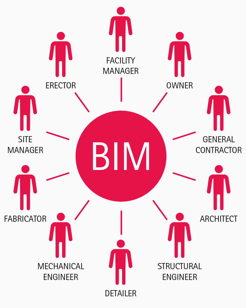
According to Littlefield (2012), BIM system brings together various professionals who need to share information in order to complete a project successfully and as per the expectation of the owners and approving authorities. When using this model, every professional will need specific software that is relevant to his or her area of specialisation. The diagram below shows the professionals involved at every stage of the project.
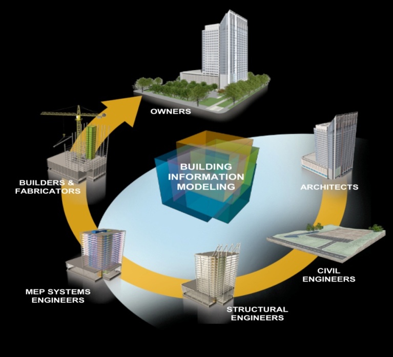
As shown in the above figure, the architects come at the conceptual stage of the project where the idea of the client is transformed into a plan that can be implemented. It is important to note that the architects play the most critical role in the BIM system because they have to generate the digital representation of the structure. Other professionals will base their work on the digital representation given by the architects. As such, it is important for the architects to have highly effective software to do this important work. ArchiACD has been one of the most popular software used by architects. Other available software includes MagiCAD, Autodesk Revit, Trimble SketchUp, Synchro PRO, and VectorWorks (Littlefield 2012).
The civil engineers will also need software to help them move the project to the next stage during the implementation phase. These engineers largely depend on Autodesk AutoCAD and Autodesk DWG for the purpose of their design and initiating the process of construction in line with what was proposed by the architect. The next stage, as shown in the figure above, is for the structural engineers who are responsible for the development of the structure to the required heights. The structural engineers uses Autodesk Revit, Autodesk 3DS Max Design, and Autodesk Navisworks Manage to ensure that they move the project from the stage where the civil engineers left it to the final stage of vertical development (Eastman 2008). The next stage of the MEP (mechanical, electrical, and plumbing) engineers to ensure that the proper fixtures and fittings are put in place in the building as per the expectations of the client. They have to go as per the plan presented to them.
Autodesk Building Design Suit Premium, Autodesk Revit, and Autodesk 3DS Max Design are the popular software used by the MEP engineers. Builders and fabricators also need software to guide them in their work as they prepare the building for occupation. Tekla Field3D, Tekla BIMsight, and Tekla Field3D are some of the software among the builders and fabricators. The building is finally handed over to the owners when it is ready for occupation. Once the building is handed over, the owners will need to maintain it properly and ensure that it is used as per what was agreed upon in the plan. GSA Spatial Template helps owners in the classification of areas and rooms as per the GAS (General Structural Analysis) Space Assignment Guide Analysis (Littlefield 2012). It is important to ensure that all these stakeholders use types of software which are compatible. This is necessary because of the integrated nature of BIM system and the fact that one stage in the project leads to the other.
Appraising Similar BIM Cases
The modern constructions are increasingly using BIM system to ensure that the unique needs of clients are met within the constraints of time and available resources. Modern architecture is taking completely new dimensions, and a number of BIM cases that have been witnessed in the past demonstrate that clients are now demanding more that beauty and functionality. One such structure is the Haydar Aliyev Centre in Baku, Azerbaijan. The building is shown in the figure below.

Completed in 2013 and sitting in an area of 101801 square meters, the building was designed in the shape of a shark. This is a clear demonstration that clients currently want to make a point in their building. Saffet Kaya Bekiroglu, the project’s architect, was able to understand the need of the client and then designed a structure that met their specific needs. Besides the functionality, comfort, and beauty of the structure, it is also passing a point about the owner’s love for shark. Another unique building that clearly indicates that BIM system is moving the world to the next level in terms of design, cost and time management, and clients’ specific desire is the Manchester Civil Justice Centre shown in the figure below.

The building was designed to deliberately defy gravitational force and with beauty that makes it fit very well within the neighbourhood. In terms of functionality, it meets the needs of the clients perfectly well. The courtrooms, the chambers, and other offices needed by various officials are perfectly designed. Since 2007 when it was completed, it has completely changed the skyline of this city.
Feasible BIM System for the Project and Its Advantages
Building Information Modelling is an emerging concept that is completely changing the field of structural design and construction (Pica 2015). It facilitates collaboration of architects, engineers, project managers, and facility owners from the initial stage of concept development to the final stage of construction when the facility is finally handed over to the owner. It facilitates exchange and management of information among the stakeholders as shown in the Shard project. The system makes it possible to conduct feasibility of the project at the initial stages before the actual work can begin. The proposal given through BIM system is often feasible. In the Shard project, the proposed design was developed in a digital form showing all the physical structures of the building and its functionality. The project owner was could see, in virtual form, what to expect once the project is completed. The design makes it easy for the engineers to know how each step in the construction process should be taken. The quantity surveyors’ work is also simplified because of the virtual representation of what is needed in the project. One of the biggest advantages of BIM, as was witnessed in the Shard project, is that it enables the stakeholders to make changes at the planning stage. This process ensures that the planned construction is completed within the planned budget. Banihashemi (2012) says that when used appropriately, BIM system eliminates unplanned expenditure. Everything that is needed is clearly outlined in the plan. In the Shard project, there was an increase in the cost by £ 85 million because of the 2008 global economic recession that affected Europe.
List of References
Banihashemi, N 2012, The Integration of Industrialised Building System (IBS) with BIM: A concept and Theory to Improve Construction Industry Productivity, LAP LAMBERT Academic Publishing, Saarbrücken.
Eastman, C 2008, BIM handbook: A guide to building information modelling for owners, managers, designers, engineers, and contractors, Wiley, Hoboken.
Ecton, E 2012, Project jackalope, Chronicle Books, San Francisco.
Gohn, G 2009, The ICDP-USGS Deep Drilling Project in the Chesapeake Bay impact structure: Results from the Eyreville core holes, Geological Society of America, Boulder.
Littlefield, D 2012, London (re)generation, Wiley, Chichester.
Pica, M 2015, Project life cycle economics: Cost estimation, management and effectiveness in construction projects, Cengage, New York.
Appendix
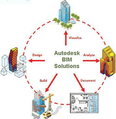
Appendix 1: Autodesk BIM solution
Appendix 2: Stakeholders in a BIM system
Appendix 3: The initial sketch of the Shard
