Overview Of The Dialysis Water Purification System
Water used for medical purposes must be clean, safe and devoid of any chemicals. Treating raw water for medical use requires the extraction of impurities in different stages. In the dialysis process, water purification is a critical factor.
Clean water devoid of any chemicals and impurities must be supplied to ensure that the water injected into the body is clean. The plant under study in this case used two main processes for purification of dialysis water; these are distillation and the reverse osmosis process. These are discussed below
Distillation process
This is the first stage of the treatment process. The main equipments for the distillation process include:
Feed pump: this is used to feed the water into the tank and ensure that the correct pressure is maintained throughout the purification system.
Boiler: the boiler is used to heat the water. The boiling process kills most bacterial and also eliminates chemicals with boiling points higher than that of water.
Heat exchanger: the evaporated water from the boiler is passed through the heat exchanger where it loses heat to the working fluid/feed water in the heat exchanger. The heat exchanger allows condensation to take place.
Reverse osmosis (RO) treatment
This is the second stage of the treatment process, the main equipment include:
Reverse osmosis feed motor: this pump ensures that water is pumped to the right pressure throughout the reverse osmosis plant.
Sand filters: sand filters are used to remove all the sediments and particles in the water. A series of slow and fast sand filters are used. Normally, water is passed through a sand bed to remove suspended particles.
Carbon filtration: since the reverse osmosis plant cannot remove chlorine and chloramines, carbon filters are used to remove them.
RO plant: this is at the heart of the treatment plant. It uses reverse osmosis to remove impurities from water.
Ultraviolent (UV) disinfection: the UV disinfectors are used to remove bacteria and other pathogens not filtered by the RO system. Other sterilizations methods are also used to ensure that all bacteria and viruses are removed.
Storage tank: clean water is stored and then passed through sterilizers before be used for dialysis.
Shell And Tube Case Study
Introduction
One of the main components of the water purification system was the shell and tube heat exchanger. This heat exchanger was used to transfer the heat from steam to the feed water causing condensation. In the shell and tube heat exchanger, the heat energy in the fluid is exchanged. That is, heat in steam is transferred to the feed water flowing through the heat exchanger.
The process of distillation is slow and uses a lot of energy due to the boiling and condensation taking place. It is therefore prudent to improve the efficiency of the shell and tube heat exchanger so as to ensure effective cooling process and utilization of energy. In this case study, an evaluation of the shell and tube heat exchanger was done so as to identify inherent problems and develop solutions to improve efficiency.
Description of the shell and tube heat exchanger
The shell and tube heat exchanger allows heat transfer between two different fluids. Normally, the feed water or the coolant flows through a series of small tubes running axially along the exchanger. The steam on the other hand, flows inside the shell. As the feed water passes on these small tubes, it extracts heat from the steam causing cooling and condensation. Figure 1 below shows the sketch of shell and tube heat exchanger used.
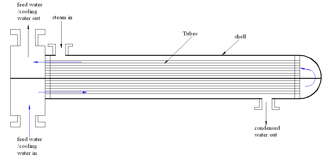
Figure 1: Sketch diagram of the shell and tube heat exchanger that was analyzed
Problem identification
During the internship, I studied the heat exchanger so as to identify some inherent problems with the system. Reduced cooling efficiency was found to be the biggest problem with this heat exchanger. It was observed that the cooling rate was not sufficient and the final water temperature was high.
Full condensation was not attained as evidenced by a little amount of steam escaping through the condensed water outlet. The heat exchanger was therefore not efficient. Further evaluation revealed that the main problems with the heat exchanger were:
The flow of dialysis water in the tubes
It was noted that the flow of water in the tubes was not optimal. It is important that the water being distilled flows at an optimum rate so as to ensure that most the heat is extracted from the steam to cause condensation and cooling to the right temperature.
The flow of cooling water inside the shell
The flow of the cooling water inside the shell was not optimized. The flow should be optimal so as to ensure that it extract all the heat from the water being purified.
The tube and shell materials
The tube and shell materials did not allow a complete exchange of heat between the feed water and steam being distilled. This shows that the heat exchange between the materials was not optimum.
Solutions to the problems
In order to improve the efficiency of this heat exchanger, several solutions were developed. These solutions are discussed below:
Optimization of the steam flow rate
For efficient cooling, the flow rate of steam should be optimized. The steam flow rate should allow maximum transfer of heat from it to the coolant (feed water) circulating inside the shell.
Optimizing the flow rate of the coolant inside the shell
To improve the cooling, the coolant should be circulated at an optimal rate. This will ensure that the cooling fluid extracts heat from steam.
Increasing the number of baffles
Increasing the number of baffles in the shell enables the steam to pass over the tubes a number of times. This will increase the cooling rate and increase the efficiency of the cooling process. This is shown in figure 2 below
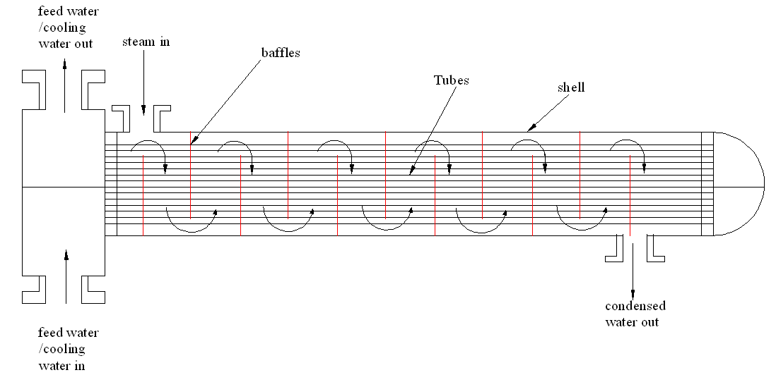
Figure 2 showing the shell tube with many baffles. The increase in the baffles will increase the flow of steam on the tubes increasing the heat exchange surface area. This will increase the efficiency of the exchanger
Increasing the number of passes (from double pass to four pass)
The current heat exchanger was a double pass shell and tube heat exchanger. In this process, feed water passed through the system only twice. To increase efficiency, the feed water should pass through the exchanger four times so as to increase the efficiency of cooling process. This is shown in figure 3 below.
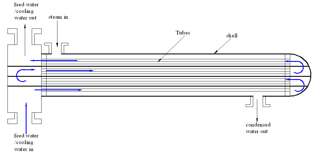
Figure 3 showing the suggested improvement changing the shell and tube heat exchanger into a four pass boiler allowing the feed water to extract more heat from the steam during distillation
Increasing the number of baffles and the times feed water passes through the pipes.
Another method of increasing the cooling efficiency is to increase both baffles and the number of times the feed water passes through the exchanger. Increasing the two will increase the contact between the cooling water and the steam been used for the distillation process. This is shown in figure 4 below
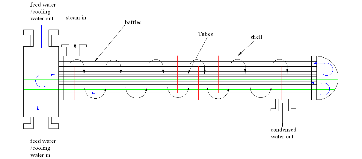
Figure 4 Increasing the feed water and the feed water circulation path.
Cleaning of the tubes
Normally, the surface of the tubes forms the heat exchange point between the steam and feed water. If the coolant flowing inside the shell is not clean, impurities are deposited on the surface of these tubes. These impurities are bad conductors of heat and they reduce the heat exchange process and efficiency.
It is recommended that regular cleaning of the exchanger be done. The surface of the tube also becomes oxidized due to corrosion. It is therefore important to use chemicals when cleaning so as to remove these oxides.
Reverse Osmosis Membrane
Reverse osmosis system
Reverse Osmosis (RO) membrane uses the principles of osmosis to perform the filtration. In osmosis, a semi permeable membrane allows some molecules to pass through and shield other molecules from passing through. In the natural osmosis process, water molecules pass through the membrane to a salty concentration. In the reverse osmosis process, the water is pumped out of a more salty solution.
In the RO process, energy is applied to a salty solutions and this is used to push the water molecules through the membrane. During the process, salt, pathogens, organic materials and bacterial don’t pass the semi permeable membrane. After active pumping, only water passes this membrane.
This allows the filtration of salts, pathogens, inorganic materials, organic materials and bacteria. The reverse osmosis membrane acts as a sieve that prevents water contaminant from passing through. The RO system can be described by the schematic diagram shown in figure 5.
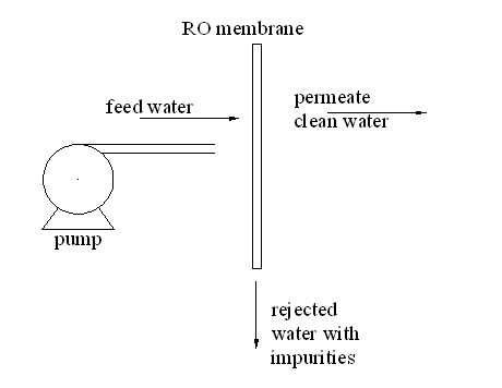
Figure 5: Schematic diagram for the reverse osmosis plant
From the diagram, the motor pumps contaminated water to the membrane which only allows water to pass leaving the contaminants. RO is able to remove 99% of the contaminants in water. The efficiency of the extraction process depends on the RO membrane, the size of the particles and the charge.
Contaminants with great ionic charge are easily filtered by the RO system as compared to those with a one charge such as sodium ions. Though RO is an effective filter, it does not remove all bacteria’s and viruses due to size. Gases also percolate through the membrane. The resulting water has low pH due to the presence of CO2 gas. To determine the performance of the RO system, the following parameters are important
- The pressure of concentrate, feed and filtered water
- The conductivity of feed and filtered water
- The flow of the feed and permeate water.
- Temperature of the system
Successive filtration
Some RO systems have the first and second stage extraction. In these systems the feed water is purified in the first stage and clean water extracted. The rejected water is passed through another filter that further removes clean water. RO can have up to six filtration membranes.
RO parameters
RO has a number of parameters that determine is efficiency. Some of these factors include:
Salt rejection: It determines how efficient the salt extraction process is.
Salt rejection =
Where Cf is the conductivity of feed water and Cp is the conductivity of the permeate water. High salt rejection means that the system is efficient in removing the contaminants.
Recovery rate: it measures the water being recovered. The higher the recovery rate, the lower the water wasted to the drain.
Recovery rate% =
where Pf is the permeate flow rate and Ff is the feed water flow rate. Most RO have a recovery factor of 60-85%.