Abstract
The demand for electric energy has been on the increase both in the industrial and domestic cycles. This rising demand implies that additional generation stations ought to be put in place. The latter is flexible and allows interconnection with Renewable Distributed generation. Nonetheless, integrating distributed generation to power systems may lead to myriads of technical challenges such as the system stability.
The integration of distributed generation challenges can be lowered by employing the concept of Smart Grid. This piece of research essay focuses on system stability and the impact of interconnecting distributed generation into Smart Grid systems.
This was executed by simulating various perspectives of the grid. In addition, examining the primary stability parameters of the IEEE 9 bus test system is critical in this paper. The paper also investigates the effects of renewable distributed generation on power system stability and distributed generation on Smart Grid technology.
Introduction
Since the modern world has advanced in terms of technological well being, the production and dissemination of electric energy is critical to several economic sectors across the globe. Besides, the use of fossil fuels is quite rampant in the modern electricity generation and transmission of electricity.
However, these fossil fuels have proved to be significantly inefficient due to the growing demand for clean sources of energy. Besides, there is inadequate energy supply across the globe. This has increased pressure on natural resources. Power loss in terms of energy transmission has also been rife. The main cause of this loss is lack of efficiency.
This power grid should be in a position to meet quite a number of requirements as far as energy production and demand are concerned. When electric grids are being loaded, the use of smart grids technology is highly effective. Load levelling of the grid can be executed more effectively using this type of technology.
It is one of the technologies that can be used to generate clean sources of energy thereby limiting the evolution of carbon-emitting gases (Department of Resources, Energy and Tourism, 2011).
Development of Smart Grid
Smart Grid is an integral aspect in the growth and development of electricity production. Scientist drawn from developed economies were among the first experts who tried to work on smart grid. Irrespective of the challenges that they went through, significant success was attained. Other nations have followed suit in the development of smart grid technology.
Some of these countries include Australia, South Korea, Canada and China. There are quite a number of smart grid research-driven factors that take place at the national level. These include energy and environmental challenges, complex grid structure, lack of improvement on safety and efficiency of the power grid operation, and poor service quality of the entire power industry.
Statement of the problem
There is a steady rise in renewable distributed generation. Therefore, it is being integrated into the power system network in order to suffice the high demand for electric energy. As a result, myriads of challenges regarding the power system stability and more specifically voltage stability may be experienced.
In addition, disturbances in the power networks might be an issue that DG units are not adequately equipped or prepared to handle effectively. Therefore, smart grid technology should be embraced so that the current challenges may be reduced.
If modern technology in the production of electricity is not adopted, then the current challenges may continue to hamper the needs of consumers and the expected profitability expected from this type of establishment.
Structure of the Report
There are seven sections in this research paper. The growth and development of smart grid has been tackled in the first section. In the second section, further information about the smart grid has been explored in order to assist in comprehending the concept of smart grid as well as the requirements.
The solar energy and integration to power grids has been explored in the third section while the fourth section offers some basic description of Static VAR Compensator and how it works.
In section five, Case studies, the set up of Smart Grid experiments, outcomes of simulation and discussions have been addressed. Lastly, the final section has been used to summarize the paper desire for future research that can be carried out to expand this body of knowledge.
Background Theory of Smart Grid
Definition
Smart grid has been defined differently in various schools of thought. According to the Ontario Smart Grid Forum, smart grid is a contemporary form of technology that makes use of computing knowledge in order to boost the efficiency of producing electricity (Murphy, 2010)
On the same note, the National Association of Regulatory Utility Commissioners (2010) indicates that the smart grid can be defined as a system that can be employed in the production of electricity by connecting and putting into use the seamless communication system. Such a system is capable of collecting and storing vital information that can later be used to transmit intelligent information in the course of generating electricity.
Smart Grid benefits
Benefits in implementing smart grid could be as follows:
- Reduction in congestion and accumulation cost.
- Minimal likelihood of blackout and compelled power interruptions.
- Reduction in restoration time, operations and maintenance due to predictively.
- Analytics and self-healing attribute of the grid.
- Reduce the price of electricity.
- Create new products and services.
- Decline in pinnacle demand.
- Improves the incorporation of distributed of the quantity of electricity generated before being utilized.
- Enhanced level of the much needed security
- The improved flow of power leads to capacity improvement, system availability, reliability and power quality.
- Efficiency due to increased capital investment.
- Electricity users have new alternatives for controlling their cost and consumption of electric energy.
The Main Features of Smart Grid
According to Xue-song et al (2010), the key features of the smart grid technology include the following:
- Self-healing: It is continuous on-line assessment and pre-control of power grid failure, as well as the failure of the automatic recovery.
- Interactive: The system can achieve the intelligent interactions between grid Corporation and customers to achieve energy flow, information flow and capital flow two-way interaction.
- Strong: Namely better identify and respond to man-made and natural disasters, protection, information security.
- Optimization: Means Improve asset utilization, effective in reducing operation and maintenance costs and investment costs, reduce power losses.
The Smart Grid Capabilities
Demand Response
The above can be defined as the process of controlling the quantity of electricity that is required by consumers. The latter is achieved by making use of real-time data. This type of response may be depicted in various ways.
For instance, the cost of electric energy at the point of distribution and the manner in which consumers behave are critical when responding to demand factor. It is possible to automate the system by integrating smart appliances and customer devices that often respond to signals remitted from the utility based on system stability and load parameters.
Distributed Generation and how it can be facilitated
In order to enhance the distributed generation, proper planning and management is required. Elements of the smart grid permit movement and measurement in both directions. Therefore, it permits generators that are located locally to produce electric energy that can be transferred to the grid system. The amount of energy produced should be compensated for accordingly.
Optimization of Asset Use
Losses in energy can be minimised by the monitoring process. The entire system has the ability to minimise energy that may be wasted during the whole process of generating electricity. In addition, monitoring makes it possible to make timely maintenance of the system and environmental protection.
Problem Detection and Mitigation
There are myriads of customers who utilize electricity that have not come into the realisation of the minimal data that can be accessed by those who operate the grid. The most vital part of this information is found at the level of distribution. Whenever there are power outrages, the calls made by consumers are given special mapping that eventually aids in identifying the regions affected by the blackouts.
As a result, the affected switches, transformers and transmission lines are then repaired by engineers on duty. As a matter of fact, it is common for customer care representatives to request callers to investigate whether the neighbourhoods have been equally affected by the power outage. This does not imply that the transmission systems lack proper monitoring systems.
There are quite a number of energy management systems such as SCADA that have been employed in the past even though they are not very effective in regards to thorough visibility. In some cases, the capacity of the grid is usually overloaded up to even four times its ability (Moghaddam & Seifi, 2010).
Nonetheless, the distribution network and a real time model will be needed by those who undertake dispatch work so that the following three competencies can be met.
- Instantaneous monitoring and reaction.
- Expectation or carrying out effective forecasting
- Carrying out the process of isolation whenever inadequacies are noted.
Smart Grid Technologies
The concept of smart grid has been categorised into several groups. Examples include
SCADA/DMS (distribution management systems), designing advanced control methods, advanced sensing, metering and measurement devices and technologies, Real-time situational awareness and analysis of the distribution system, Substation automation (SA) and designing main and local supervisory control units along with suitable human interfaces and integrated communications
Grid technologies have the following requirements:
Integrated communications
The process of making decision and flow of information is facilitated by the standardized and high-speed system attached to the grid components.
Measurement and Sensing
This component makes it possible for users to give instant feedback based on the information obtained from energy producers.
Advanced elements
This type of technology is capable of enjoying several latest technological platforms in the production and distribution of energy.
Advanced methods of control
Information is gathered, stored and analysed more easily by the advanced control systems of the grid.
The Integration of Solar Energy with the Smart Grid
Introduction
Solar energy is received on the surface of the earth on a daily basis. There is adequate amount of energy that emanates from the sun at any given time.
In addition, it is pertinent to note that energy conversion in a solar thermal plant starts with collecting the sunlight, converting it into heat which is then powering a thermodynamic engine. In the last stage, the engine drives a generator which produces the electricity. The heat conversion path is similar to any other conventional fossil or nuclear power plant.
Merits of Solar Energy
Economic merits
- Fast installation since the process is not complex
- The energy curve is predictive
- No complex infrastructure is required during installation
- Highly reliable especially when used for a long time
- The pricing is predictable and easy to determine
Environmental merits of Solar Energy
- does not pollute the environment
- Compatible with several geographical regions
- Relatively cheap and efficient
Social merits of Solar Energy
- Limits energy disruption and thus enhance national security
- Increases the independence of a nation in energy production
- Decent local employment opportunities are created
- Conserves other natural resources such as water.
Photovoltaic
Background and definition
This form of electric energy is made up of cells that can transform radiation from the sun into direct current. A material that is receptive of solar radiation is used to convert the raw energy from the sun into a direct source of electric energy. Doping is carried out on the material so that the charge carriers can be increased. These carriers can either be negative or positive. There are several panels used to make Photovoltaic systems and they may be arranged either in series and parallel.
Types
The PV power systems are categorised into three typical configurations. These are grid-connected, hybrid and autonomous.
Stand alone applications make use of both the hybrid and autonomous systems and are mostly applicable in locations that cannot be easily reached. However, the grid-connected systems, the generation of electricity is undertaken where it is supposed to be used.
Later on, the transportation and distribution capacity can be improved. the excess power can then be fed into the national grid system for future use (Australian Clean Energy Council, 2011).
Solar Energy Integration with Smart Grid
Operational methodologies that are advanced and high-tech are required when running solar energy systems that are driven by weather. However, in the case of the fossil fuel plants which are conventional in nature, the requirement of the power system is always put into consideration.
It is imperative to mention that variability exists whenever solar energy is used in the production of electric energy. For instance, the alteration of fuel supply is a major determinant when solar energy is used in the generation of electricity. This implies that regulating the solar system is quite cumbersome compared to the conventional system.
Challenges of Integrating Solar Energy
Fluctuation in the amount of Voltage
When solar energy is used in generating electric current, the main challenge that is usually experienced is the fluctuation in voltage. When fluctuation takes place, the delicate electric equipments are affected as well. As a result, the durability of such equipment is significantly lowered.
Harmonic Distortion
The power system grid is usually injected with harmonics using the electronic devices. When distortion in harmonics takes place, distortion in voltage also occurs. Therefore, the operating harmonics ought to be minimised significantly when the grid is being used. The required range of harmonic distortion should be used so that the overall harmonic distortion is reduced to the minimum.
In order to reduce the distortion in harmonics, an appropriate design of the control algorithm should be adopted. Better still, it should be done on the control loop being used at that particular time. There are quite a number of filter types that cane employed in order to lower the interruptions. These have been explained below:
Reactive Power Compensation
The power systems are affected by induction generators that usually consume reactive power. A lot of reactive power is consumed by induction generators bearing in mind that there is a gradual increase in the amount of power generated. This implies that the demand level and reactive power should be brought as close as possible to each other. A fixed capacitor can then be used in order to attain a typical power compensator.
Synchronization
The production of high quality power has been a key area of concern for a lengthy period of time. Some of the common research challenges include phase, voltage and grid frequency. The phase-locked loop (PLL) is the key method of synchronization. In addition, the non-linear transformations, filters and grid voltage detection can also be used.
Storage of energy
The ability to deliver power without significant disruption is a crucial factor when considering energy storage options. When electric energy is produced using energy from the sun, there are lots of uncertainty and instability.
This explains why the storage system adopted should be as reliable as possible. Surplus energy should be stored in order to meet demand when power is unstable. Some of the storage facilities used include the superconducting magnetic energy storage, super-capacitors, flywheel and batteries.
Scheduling and Forecasting
The long term weather patterns should be known so that the variability of solar energy can be established. The smart national grid can only be penetrated if the weather patterns are understood well. The network security should be safeguarded at all costs in order to lower the intermittent energy. Forecasting and scheduling should be done in the most accurate manner.
Load Demand Management System
Uniform supply of energy is critical in the entire production of electricity. Therefore, it is necessary to understand that solar energy is intermittent and as such, should be planned and managed in the best way (Energy Response Pty Ltd, 2011). Energy can be significantly wasted if the load and output of solar energy are not made compatible.
Distributed Generation
Definition
When the source of electric power is directly linked to the network of distribution in order to reach consumers on the other end, it is referred to as the distributed generation. However, the generation source rating is not included in this definition (Rujula et al.,2008).
Technologies of Distributed Generation
Table 2: Sizes of distributed generation modules (Rujula et al.,2008).
The Penetration of DG
It is necessary to design the network in such a way that the distributed generation can be embraced. The equipment technology will undergo new demand especially if the small power generators will be used in the production of electricity. Hence, communication concepts and novel management units will have to be developed in order to enhance the process of distributed generation.
Moreover, the low reserve capacities will be coupled with the installation of the electric equipment in a new environment. The ability to secure network stability ought to be part and parcel of the on-going research activities.
In any case, there are several fluctuating generators that are being used to produce power even though they are not reliable or stable at all. Supply reliability can only be attained if the fluctuating generators are improved using the latest set of technologies.
The most appropriate mix in energy is also a vital pre-condition that ought to be put into consideration. If the planning process is proper coupled with efficient communication and directional energy management, it will be possible to attain the most accurate energy mix. Communication technology should also be advanced accordingly. Some of the technical constraints include:
- Technical hindrance of the existing network
- Design methodologies
- Safety concerns
- Auxiliary equipment and potential disturbance.
- Control protocols and complex metering
It is necessary for utilities to assume the following features in future:
- Site demand loads should be connected and gathered properly
- Tools needed for simulation and modelling ought to be developed and improved
- The voltage grid that supplies low amount of electric energy ought to be improved.
- The energy grids should be strengthened and re-designed.
Power system stability
When the planning process is on-going, analysing the stability of a smart grid is critical. The same system of analysis is also required during both the operation phase and the design phase of the smart grid technology. There are quite a number of methods that can be used to interpret the stability of an electric power system.
Both the status of operation and system configuration determine the type of analytic method to be used. The manner in which the system performs under different situations is evaluated using the methods adopted.
In order to define the strength of a smart grid, both of the aforementioned conditions ought to be assessed thoroughly. In case any faults are noted, it is possible to restore the condition of the system. This can only be necessary when dynamic features of the grid are understood well.
There are two categories that can be used to classify the aspect of stability. These include the transient and steady state types. When large scale production of electric energy is required, synchronous generators are used. These generators also ensure that parallel operation can be executed effectively.
The ability of a system to remain stable for a significant length of time is necessary since there is increasing demand for electric energy. There are three classifications of stability analysis as noted below:
- The stability of Rotor Angle: this entails both the tiny and large stability types that are anchored on rotor angle.
- Stability of the voltage: this consists of both the small and large disturbances.
- Stability of the frequency: encompasses both the short and long term stabilities.
The three types of classifications are particularly necessary when the smart grid technology is being adopted for bulk production of electricity. In addition, all the above classifications are workable when stability of the system is kept on check or controlled.
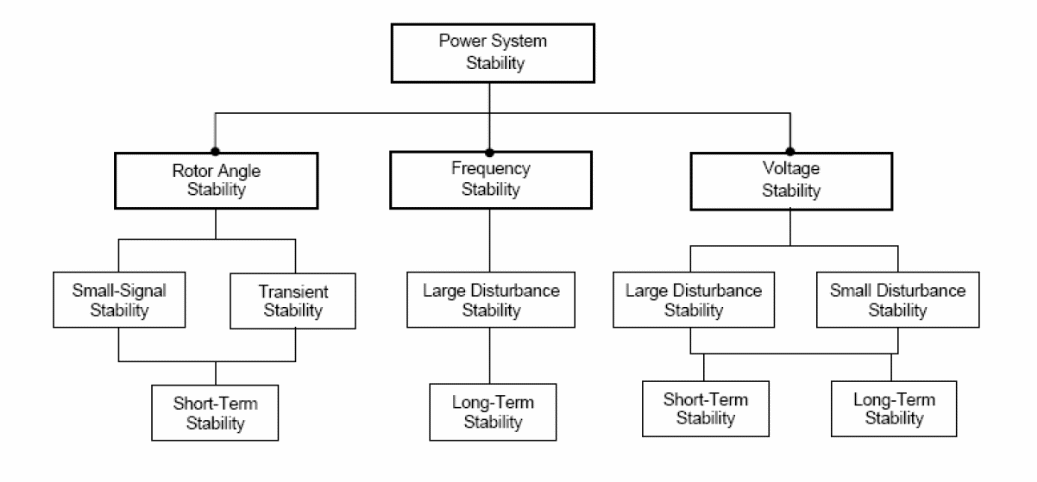
Stability in voltage will be integral in the following area of discussion since power system stability is a critical part of a grid system.
Stability in Voltage
When the desired amount of voltage is permitted through a system without any form of significant fluctuations, it is referred to as voltage stability. All the buses are supposed to be supplied with permissible range of voltage at any given time. Hence, severe system perturbation should not be allowed to take place within the system at any given time.
When some buses receive remarkable fluctuations in the amount of electric power that passes through them, instability may take place. However, voltage drop is the main cause of voltage instability within a system. This usually takes place power flows that are both reactive and active are inducted through power lines. As a result, voltage support across the power lines that are used to deliver electric energy is limited.
In other words, power cannot be transferred easily without experiencing challenges. Furthermore, voltage instability can also be occasioned by dynamic loads especially when any slight disturbance takes place. When the consumed power is restored, a response is received by the load. This may boost the consumption of reactive power. Worse still, additional reduction in voltage may be caused by extra pressure on high voltage network.
There are two distinct classifications of voltage stability. The first type is referred to as the large disturbance while the second one is known as the small disturbance.
In the first case, large perturbations can be regulated by a system. Examples of large perturbations include failure in the system and diminished generation. In the case of small disturbance stability, small perturbations can be swiftly regulated by a system. A typical example is the load change that takes place in a gradual upward trend.
Challenges posed by voltage stability may take a few seconds to several minutes before coming to an end.
Stability of the Grid and Effects of Distributed Generation
Voltage is increased at the grid when the photovoltaic DG is integrated to the grid system. This addition is supposed to take place between the utility grid and the DG where the PCC is positioned. It is possible for unacceptable level of voltage to rise especially if there is coincidence between light load demand and the optimum power production at the PV.
When the later is not controlled in good time, it may occasion system instability or destroy the neighbouring equipment. Moreover, the grid voltage is influenced by the presence of PV DGs to the system especially when the grid is in its normal working condition.
Methods of Analysis
The investigations into the impact of distributed generation on power system stability by looking at voltage stability will be carried out using power system simulation software. The software must be capable of performing different voltage stability simulations and therefore must carry out complex nonlinear calculations.
For this reason, the Power Factory software (DIgSILENT) will be used in order to achieve the desired simulations as well as building and modelling test power systems and electric generator models. DIgSILENT is a powerful simulation tool which will provide the majority of the stability analysis for the work carried out on this paper.
The system that will be used the simulation in this paper is based on the standard IEEE 9 node test system (Kumar et al, 2012). This test system has also been provided with data for the transmission lines, transformers, bus voltages, and load power (see the appendix).
Using Static VAR Compensator as a smart grid
In order to supply the load demand, it is necessary to appreciate the aspect of renewable energy and demand of electric energy at any given time. Both the input and output in voltage is also expected to be relatively stable. The effects of distributed generation can be minimised when the grid system is upgraded. In order to improve the stability of voltage, SVCs were employed.
Background
It has been shown previously that large or small penetration of distributed generation may cause some significant issues regarding the power system stability. The system may be grossly experience destabilization due to quite a number of factors. For example, when the reactive power is not regulated appropriately, it may lead to system instability.
This challenge can be managed by making use of a reactive power compensator that is shunt in nature. A good example is a system that has been made using the SVC technology. The latter is controlled by a thyristor. It has no gate turn-off capability. A response time is also offered within a very short time.
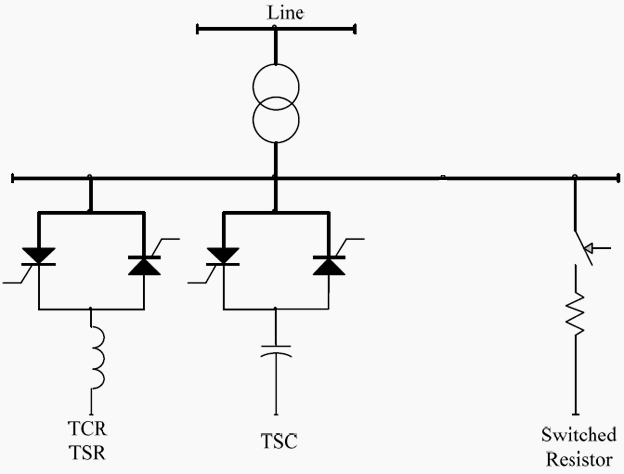
Figure 5.1: Basic Structure of SVC (Watanabe, 2007)
From the above figure, it is evident that the SVC I made up of the following aspects:
- Capacitor that has been switched using a thyristor
- A reactor that has been switched and controlled using a thyristor
Both the above components are made up of a reactor that has been to a shunt and is regulated using a thyristor that has been connected back-to-back and in a parallel system. When a phase angle control is employed, a non-changing reactive power is generated by the TCR.
The amount generated ranges from 0 to maximum. On the other hand, the phase angle control is not required when controlling the TSR. As a result, resistance is changed and thereafter a constant inductive admittance is offered. The operating features of the TSR are quite similar to its composition (Watanabe, 2007).
Control of SVC
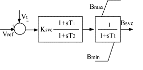
Figure 5.2: Block diagram of SVC controller (Alinezhad and Ahmed, 2009)
From the above figure, we can see that the SVC is shown.
Key
Vt is the amount of voltage that passes through the controller.
Vref is the amount of voltage that is supposed to be retained through the control apparatus.
KSVC refers to the gain of regulator
T1 and T2 refer to the values used to adjust the gains.
Bmax and Bmin are used to denote the range compensated by the controller
BSVC refers to the absolute susceptance of the controlling device.
In order to calculate SVC, the following formula is used:

Eq. (5.1) (Tahri, 2000)
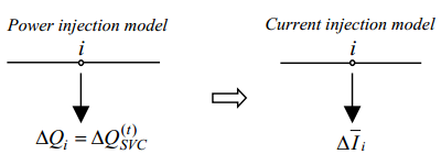
Figure 5.3: Mathematical Model of SVC (Tahri, 2000)
Voltage Stability Enhancement
As it was suggested that the SVC could be used to enhance the voltage and improve the stability of the power system (Yome et al, 2007). From the diagram given below, there is a lparticular trend in the aspects of receiving voltage. For instance, the lag ranges from zero to nine while the lead aspect ranges from zero to nine as well. Voltage instability is represented by dashed lines with maximum values.
The condition of the system is also responsible to this voltage stability. The manner in which voltage is received has been shown in figure 5.4. Voltage collapse can take place when the nominal rate is surpassed by the voltage limit. Therefore, the voltage stability margin can be enhanced significantly by regulating the terminal voltage.
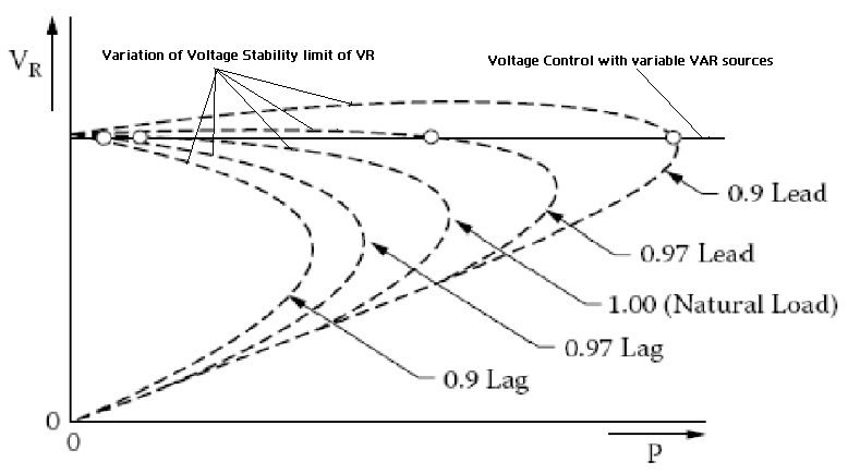
Figure 5.4: The characteristics of receiving voltage end (Tahri, 2000)
Experimental Setup and Results Analysis
Network Model
The power system, figure.1 that was used to perform the simulations was based on the standard IEEE 9 node test system (Kumar et al, 2012). This test system has also been provided with data for the transmission lines, transformers, bus voltages, and load power. The data is provided in the appendix.
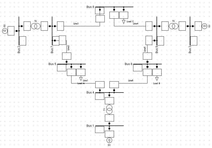
Figure 6.1: IEEE standard 9 bus test system (Kumar e.t al, 2012)
Location and Sizing of the Distributed Generation
Distributed Generation (DG) has the potential to provide technical merits such as the reduction of power losses and power quality improvement. On the other hand, it should be noted that, if the DG is misplaced, it may easily cause degradation of power quality, reliability, and control of the system or it may increase losses and affect voltage regulation.
Therefore, it is essential to consider approaches for deciding the location of distributed generation units in distribution systems. The analysis is performed on this section using a steady state power flow studies which can evaluate voltage at each node of the distribution system. Different busbars have been tested to identify the best location of DG.
A load flow solution for the system using Newton-Raphson load flow method was performed and the results are provided in the table below. The results of the load flow are used to indicate the optimal location of the DG in our network.
Table 6.1: Voltage profiles at each bus with different DG location
It could be seen from table 2 that the voltage profiles have been improved when the DG is installed at bus 5. Therefore, it could be concluded that installing DG at bus 5 is the best location on this network from the steady-state viewpoint.
Another important factor has to be considered is the penetration level of DG. The penetration level of distributed generation can be defined as the percentage of distributed generation power supplying the total system load demand (Morren and Sjored, 2008). Mathematically, it is defined as:
Penetration Level (%) = ( PDG/ PL ) x 100
Where:
PDG= DG Power
PL = Load Power Demand
The load power demand of this network is 497.45 MVA in the first three cases and the DG will be supplying 10 % of the total power demand. In the last case, the load demand power will be increased to 746.18 MVA and also the penetration level will be increased to about 15 %.
SVC Controller
The most appropriate location for shunt reactive power compensation for voltage stability is the weakest bus of the system (Yome et al, 2007). Therefore, identifying the weakest bus is essential in order to maximize the benefit of installing SVC. Voltage stability indices are several in terms of classifications. These are categorised in terms of their stability and strength. Some of those indices will be briefly explained below.
Voltage Sensitivity Factor
The system voltages are checked with respect to the change in loading, which results in a Voltage sensitivity factor (VSF).
VSF =
The magnitude of the voltage is caused by the minimal variations in loading. This leads into an increased level of sensitivity. Thus, the highest sensitivity factor indicates the weakest bus (Saadat, 2004).
L- index
A voltage stability index was developed by Kessel et al in order to seek answers for the power flow equations. The actual state distance is determined a quantitative measure of the L index. The latter measurement must also be aligned to the limit posed by the level of stability. The entire system stability is described by the L index using the following equation:

From the above equation, aL represents the load nodes while aG represents the generator nodes. On the other hand, Lj represents the local determinant which acts as the indicator.
Reactive Power Margin
In order to take an accurate bus measurement of a reactive power margin, the figure below has been used to show the procedure (Qin et al, 2009). According to Saadat (2004), the level of loading on any specific bus is indicated by the reactive power margin and can be boosted before exhaustion of the limit used for loading can be attained. Additionally, the collapse in voltage is also measured at the same time.
The differences experienced are largely occasioned by quite a number of factors such as synchronous, condensers, SVCs and reactive reserves.
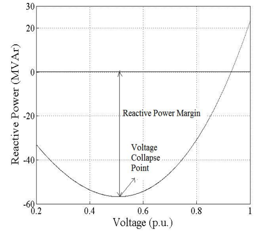
Figure 6.2: Example of Q-V curve and Reactive power margin (Qin et al, 2009).
Qin et al. concluded that the weak buses rankings using the different methods for the normal condition according to the different approaches are similar.
The technique was employed in investigating buses that were considered to be relatively weak. A code was written in DIgSILENT which was varying the load and measuring the voltage at the buses to observe the voltage deviation.
The load was increased gradually until the iteration process cannot converge which indicates the load reaches its maximum values. The table below shows the voltage at the buses when the load was at the initial values and when it reaches the maximum value.
Table 6.2: Voltage profile with different loads
In the table above, voltage profile of each bus has been obtained for different load values. It was found from the results and the simulation that bus 6 and bus 8 were the weakest bus as they have the highest voltage deviation.
Reducing the reactive power load in the system or adding new reactive generation is essential to solve this problem. Therefore, knowing the amount of reactive power support required at the weakest bus is essential in order to determine the needed shunt compensation capacity.
This could be found by placing a synchronous condenser without any limit on the reactive power at the weakest bus and observing the amount of reactive power generated at the maximum loading point (Mithulananthan and Yome, 2004).
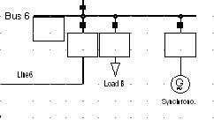
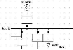
Figure 6.3: The synchronous condenser connected at the weakest buses
After connecting the synchronous condenser at the weakest buses and run power flow simulation, the optimum capacity required for SVC is 28.44 MVAr at bus6 and 40.50 MVAr at bus 8.
The test system was used to run the simulations to observe the voltage stability improvement after integrating a distributed generation with static VAR compensator.
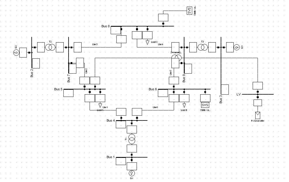
Figure 6.4: Test System with the integrated DG and SVC