Introduction
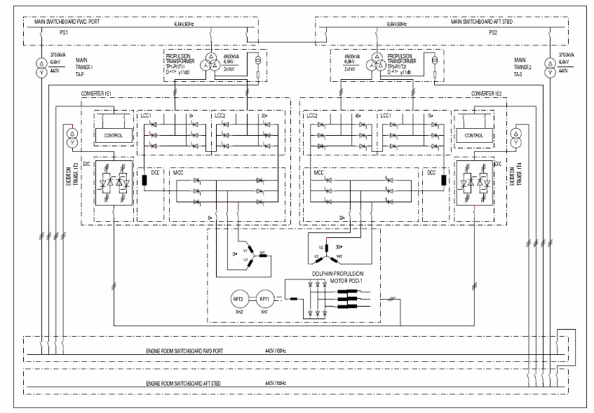
In comparison with the straight diesel drives, the systems, based on diesel-electric propulsion, are more advanced and superior from the perspective of numerous factors. Originally, this superiority has become a direct reason for the constantly increasing demand for diesel-electric drives and systems in marine engineering. The main features of the studied system 6.6 kV MSWB are the improved economic operation, the high availability of this system, and the flexibility of control, as well as the simplicity of technical maintenance.
The voltage levels will be calculated on the basis of the observation data, and the power rates will be provided for these voltage levels. In accordance with the questions of the task, the protection issues should be discussed. On the one hand, these issues provide the required safety level; on the other hand, protection is required for the control of the voltage level through the entire system. Finally, the accuracy of the simulation and calculation will be argued. The necessity and relevance of this issue are closely associated with the further destiny of the analyzed MSWB, and the necessity to consider all the possible situations and define the range of the voltage levels.
Nominal Operating Voltage and Power Factor
The nominal voltage for a High Voltage switchboard will depend on the regime of the work. In accordance with the observations, the nominal voltage for the A point of the basic circuit is close to 6600 volts. The power factor will be calculated in accordance with the following formula:
- Power Factor = true power / apparent power
Thus, the calculations will be the following:
Originally, these characteristics of the switchboard are explained by its features. The HV switchboard design offers the following main features, in accordance with Kongsberg Maritime (2008):
- Well-proven and well-known technology
- Arc fault tested according to IEC 298-1990
- Circuit-breaker mounted on a withdrawable modular carrier
- All switching operations with HV door closed
- Interlocking mechanisms of the HV door, withdrawable section and make proof earthing switch
- Protection against electric shock and ingress of foreign bodies
- Arc-tested sheet-steel enclosure or compartmentalization
- Use of service proven vacuum circuit breaker and vacuum contactor with maintenance-free interrupters
- Minimises the use of insulation materials and parts and low fire contribution (Kongsberg Maritime, 2008)
Load Regulation at the Propulsion Transformer
Considering the fact that load regulation is the capability to maintain a constant voltage level regardless of the input voltage leap, the calculation of the load regulation is the following:
- % load regulation = 100% * Voltage (Full Load) – Voltage (Minimum Load) / Voltage (Nominal Load)
Based on these calculations, there is a strong necessity to emphasize that the converter transformer, which is controlled by the propulsion transformer and fully depends on the voltage level on the input of the transformer, is the direct link between the shipboard power supply network and the drive. This part of the module is responsible for the matching of voltage levels in the entire system, consequently, the load regulation percentage is required for the proper calculation and regulation of the voltage levels in the entire system. As it is stated in Kongsberg Maritime (2008):
Here, the characteristics and mode of operation of the converter-fed drive call for certain outputs, voltages, and short-circuit reactance. Given the present state of the art, it goes without saying that the design and quality of the transformers must be such that they can operate fault-free and maintenance-free for many years. In designing transformers, three points must be kept firmly in mind: Harmonics generated by the converter, DC magnetization and possibly appearing load unbalance under fault conditions.
Circuit model of a Propulsion Transformer


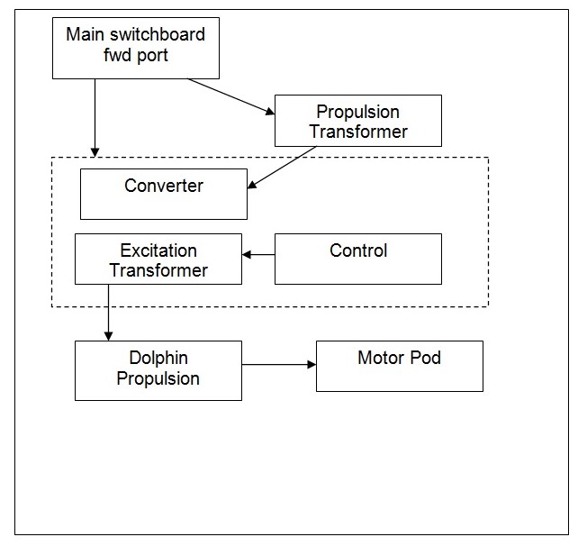
The circuit model of the propulsion transformer is created on the principle of voltage control and regulation of the power levels, depending on the working regime of the entire system. Originally, it should be emphasized that all the blocks of the model are not interconnected, nevertheless, propulsion blocks control the engine room and switchboards of the other blocks of vessel control.
50% overload
Originally, the propulsion block is created not only for voltage regulation. Control of the overload is one of its key tasks, consequently, the 50% overload credibility is close to zero. As it is stated in Simar Drive (2009):
Because it has been specially developed for rapid open-loop and monitoring of electric drives, all the medium voltage drive systems are equipped with the fully digital SIMADYN D multi microcomputer system. Successful worldwide, SIMADYN D satisfies the highest requirements for dynamic response in drive technology, including protection of the ship´s power plant by guarding the diesel generators against overloading by the propeller drive. At the same time, the protection feature ensures that the diesel is optimally loaded or offloaded according to load changes in the drive system.
Nevertheless, if overload occurs, the power will be either reset or equally allocated between the two blocks of the transformer, thus, the reserved block will be involved in the control process. If the load is too high, the switchboard will reset the power by enacting breakers, thus, the main generator and the propulsion block will be deactivated.
Relevance of the Protection Arrangements
Arguing on the matters of the protection blocks, it should be emphasized that the necessity to protect the system from high voltage and overload is actual from two perspectives. On the one hand, the system will be controlled by people (crew of a vessel), consequently, the proper protection should be provided for granting the required safety level. On the other hand, the system should be protected from the possible overloads, and, probably, the reserve transformer will be required for coping with extreme overloads. Consequently, the relevance of the protection issue is closely associated with the safety of the system, and the team, which will be engaged in the process of maintaining the entire system.
Originally, as is emphasized in Simar Drive (2009), the model of the generating block is cooled actively, therefore, the overload may damage the cooling system, and cause the breakout of the entire system. The following statement is emphasized: “The auxiliary generators are also modeled as actively-cooled permanent-magnet machines running at 3600 pm despite the fact that the auxiliary gas turbines under consideration, mainly turbines operate at much higher speeds thereby requiring gear boxes; an unlikely topology in future configurations” (Kongsberg Maritime, 2008). In the light of this consideration, the necessity to provide the additional protection system looks grounded, as the values of the safety and protection is crucial for vessels, as these systems provide the required level of vital capacity, including the vital capacity in emergency situations.
Effectiveness and Accuracy of the Simulation
As for the matters of any simulation, and the accuracy of these modeling, there is strong necessity to emphasize that it is impossible to model any situation, and consider all the possible instances, nevertheless, the accuracy of the calculations and simulation is enough for calculating the range of possible situations. Therefore, the lower and the upper levels have been considered in this paper.. As it is emphasized in Kongsberg Maritime (2008):
The best way to acquire practical experience is to learn from real life in a real engine room, but today the efficiency requirements do not allow for this kind of onboard education, hence the training has to be carried out on a simulator. Practising decision-making in a simulator environment where decisions and their effects are monitored opens a unique possibility to evaluate the effect of the decisions.
Considering the modeling of the transforming block, the value of including all the components of the circuit model is closely associated with the control system and the protection principles of the electric scheme of the transformer block. The initial modeling effort of the pre-controlled elements of the transformer box was used for finding the inadequate terms of parameter control and finding the time, required for the execution. In accordance with Simar Drive (2009):
This allows a more efficient modeling, a better control over model parameters, and helps in preventing the occurrence of algebraic loops, which are often the cause behind computation slow down during execution. Analysis examples highlighting the usefulness of the modeling and simulation approach to the design and analyses of the electric ship power system architecture were presented.
Nevertheless, in spite of the accuracy of the calculation, the simulation was not full, as it did not entail the calculation of the other parameters, and the possible range of these values. Nevertheless, in accordance with the technical documentation (Simar Drive, 2009), these parameters are the following:
Conclusion
Finally, it should be stated that the calculations of the voltage levels and the power rates of the MSWB 6.6 kV entailed all the possible factors, which may influence these levels and rates, nevertheless, the entire simulation can not be full without considering the Lighting impulse test voltage and power frequency test voltage. As for the matters of protection, these matters are aimed to protect the entire project and provide the necessary safety level for the crew.
References
Kongsberg Maritime(2008) “Neptune Engine Room Simulators” Kongsberg Maritime publishing.
Simar Drive (2009) “Advanced Diesel-electric Propulsion” Systems Industrial Solutions and Services. Marine Solutions publishing