Introduction to EMC
In this age of technology where we have the presence of electronic appliances, electrical connections, high-tech gadgets, and everything that uses electricity, there are electrical impulses or what we call electromagnet emissions all around us that we don’t feel. We are living in an atmosphere that has the presence of electromagnetic emissions, measured in Hertz, countless of these impulses, is a result of the appliances we have at home, our cell phones, computers, and everything.
Electromagnetic emissions occur because there are electrical charges all around us as a result of lightning, relays, or transformers in electrical posts, dc electric motors, and fluorescent lights, and so forth. EMC can cause distractions to these electrical appliances. Radio transmissions can cause distraction on our television. Electromagnetic waves continuously flow in the atmosphere. These distractions can be in the form of impulses emitted by numerous sources, for example, radio transmitters, but even our own appliances also produce impulses. Our movement too also causes impulses in the form of static discharges which can cause distraction, but in a limited way.
When radio transmitters or television stations transmit their signals or pulses they are received by our appliances, the television set, or the radio from their respective antennas. These pulses have their own band of frequencies, or bandwidth, in order for the appliances to receive the required signal. The bandwidths are prescribed legally, that means for every radio station, or television station, each has its own band width so that they can not be intercepted by other stations.
So these appliances produce electromagnetic emissions which cause interference in electrical and electronic devices. But they can be controlled. For example, if we set our desired station of an AM radio, we hear different garbled signals. But then, the AM radio has several filters or small IF transformers inside that intercept the required station, so that the electromagnetic emission is controlled, or the required radio station is produced. An intentional receiver is our radio with the set station, but an unintentional receiver is another electronic appliance which does not want to receive the signal, for example the TV or the computer system.
The purpose of the introduction here is to focus on electromagnetic compatibility or EMC which can be said as electromagnetically compatible with the environment if the following criteria are met:
- It does not cause interference with other systems.
- It is not susceptible to emissions from other systems.
- It does not cause interference with itself.
History of EMC
In 1901, Marconi made the first experiment on radio transmission which was a form of transformer or a set of copper wires. He used a radio receiver which had a simple mechanism to correct interference or EMC. It was an early invention, and so it was crude – antennas and receivers were simple. But interferences from motors, electric railroads, etc., became a problem.
During World War II, the problem of radio interference became a major problem. This was because of the emergence of electronic devices, radios, navigation devices, radars, that interferences could be had almost in every device. Electronics improved, and with this, more and more problems on interference occurred. Introduced into the market were transistors commonly called solid-state devices, integrated circuits, microchips, etc. The frequency spectrum became more crowded. This so-called frequency spectrum has to be planned so that each proposed EMC emission can not cause much disruption.
The computers came with the introduction of the integrated circuit. Analog signal processing became digital signal processing. Electronic functions were being implemented digitally because of the increased switching speed and miniaturization of the ICs. EMC and noise sources are now rich in spectral content. This is all present all around us that we get signals or EMC, or interference, desired and undesired.
In the United States, the one in charge for the regulation of radio frequencies or limit EMC, is the Federal Communications Commission in the United States. One of its objectives is to limit “EMC pollution” – to prevent, or reduce, the number of instances of electromagnetic interference. EMC is now the concern of manufacturers so that manufactured appliances can meet the requirements set forth by FCC, and these include EMI emitted by computers and electronic appliances. Other countries also have their regulatory bodies on EMC regulations. Countries in Europe had their own regulatory body well before the FCC of the United States. In 1933 the International Electro-technical Commission (IEC) in Paris recommended the formation of the International Special Committee on Radio Interference.
Aspect of EMC
EMC is concerned with the generation, transmission, and reception of electromagnetic energy. These three aspects of the EMC problem form the basic framework of any EMC design. The source or emitter produces the emission, a transfer or coupling path transfers the emission energy to a receptor or receiver, where it is processed, resulting in either desired or undesired behavior. “Interference occurs if the received energy causes the receptor to behave in an undesired manner.” (Paul 2006, p. 3)
There are three ways to prevent interference:
- Suppress the emission at its source.
- Make the coupling path as inefficient as possible.
- Make the receptor less susceptible te emission.
Decibels and EMC units
The decibel (dB) was originally developed in the telephone industry to describe the effect of noise in telephone circuits. EMC units expressed in decibels (dB) have the property of compressing data, for example, a range of voltages of 108 which is 160 dB.
It is important to conceptualize the values of various EMC units when they are expressed in dB, which is somewhat similar to the conversion of units from the English system (inches, feet, gallons, etc) to the metric system of units (meters, centimeters, liters, etc.).
EM FEM-Fieldory
Electromagnetic field is a magnetic field produced by current which passes through a set of wires. This magnetic field could deflect a compass needle. Faraday succeeded in showing the converse effect – that a magnetic field could produce a current.

emf equation is solved this way:
The time-changing flux, dø/dt, can happen as a result of:
- A changing magnetic field within a stationary circuit
- A circuit moving through a steady magnetic field
- A combination of 1 and 2
Vector Analysis
Maxwell’s equations are described concisely in terms of certain mathematical operations on vector quantities in three-dimensional space. The field quantities are described as vector quantities, which will be denoted with an arrow above the symbol, and a vector is represented as a directed line segment. Vector quantities convey two pieces of information: a magnitude and a direction of effect.
In order to quantitatively describe a vector and perform mathematical operations on it as required by Maxwell’s equations, we must describe the vector in a coordinate system. A rectangular or Cartesian coordinate system consists of three orthogonal planes, x = x1 = constant, y = y1 = constant, z = z1 = constant, as illustrated in the figure.

The rectangular coordinate system: locating a point as the intersection of two orthogonal planes.
Maxwell’s equation

Using Stoke’s theorem:
The spatially changing electric field produces a time-changing magnetic field. This is one of Maxwell’s equations linking electric and magnetic fields. The equation can also be expressed as:

This is another of Maxwell’s equation which shows a spatially changing magnetic field which produces a time-changing electric field. The latter dD/dt can be treated as an electric current which flows through a dielectric, e.g., in a capacitor, when an alternating potential is applied across the plates. This current is called the displacement current to distinguish it from the conduction current which flows in conductors. The conduction current involves the movement of electrons from one electrode to the other through the conductor (usually a metal). The displacement current involves no translation of electrons or holes but rather an alternating polarization throughout the dielectric material which is between the plates of the capacitor.
From the last of the equations we see a key conclusion of Maxwell: that in electromagnetic fields a time-varying magnetic field produces a spatially varying electric field and a time-varying electric field produces a spatially varying magnetic field.

Maxwell’s equations in point form:
Faraday’s law
When static conditions hold, this equation is expressed in:

But when expressed in terms of potential fields, these equations are equivalent to:

Where:
p (both free and polarization type) is the cause;
ø and E are the results;
J is the cause;
A and B are the results.
Ampere’s law

Steady currents act like “paddle wheels” that stir up circulation in the magnetic field, giving rise to B lines that look like the flow lines for whirlpools. This line integral is called out around a closed path, and I is the current enclosed by the path. Ampere’s Law is analogous to Gauss’ law in that it is useful for calculating the magnetic field for highly symmetric current distributions.
Faraday’s law and Ampere’s law may be considered duals. Faraday’s law relates the emf (the line integral of the electric field around a closed path) to a time rate of change of magnetic flux penetrating the surface bounded by the closed path. Similarly, Ampere’s law relates the mmf (the line integral of the magnetic field around a closed path) to a time rate of change of electric flux (displacement current) penetrating the surface bounded by the closed path. Faraday’s law is the basis for induced voltage sources due to self and mutual inductance.
Gauss’s law
There is a general relationship between the net electric flux through a closed surface (often called a Gaussian surface) and the charge enclosed by the surface. This is known as Gauss’s Law and is a fundamental importance in the study of electric fields. (Jewett and Serway 2007, p. 676)
The magnitude of the electric field everywhere on the surface of the sphere is
E = krq/r2
The field lines are directed radially outward and hence are perpendicular to the surface at every point on the surface. That is, at each surface point, E is parallel to the vector ∆A, representing a local element of area ∆Ai surrounding the surface point. Therefore,
We find also the net flux through the Gaussian surface, thus:

Conservation of charge
Conservation of charge involves the time rate of decrease of free charge on the right-hand side. For static conditions this is zero, and the result reduces to saying that “no charge can be stored at a point”; whatever current enters a closed surface, it must immediately exit that closed surface. But this is equivalent to Kirchhoff’s current law. We fix up Kirchoff’s current law by defining capacitance.
Constitutive parameter of the medium
We can determine the electrical constitutive parameter of a medium by using a monopole or dipole antenna, where the impedance as function of the parameter can be defined for the antenna. The impedance of the parameter is a function whose coefficient can be determined by measuring the impedance in a standard measure.
Electrical dimensions are measured in wavelengths.
Field Theory
Physical dimensions of a radiating structure such as an antenna are not important, per se, in determining the ability of that structure to radiate electromagnetic energy. Electrical dimensions of the structure in wavelengths are more significant in determining this. Electrical dimensions are measured in wavelengths. A wavelength represents the distance that a sing-frequency, sinusoidal electromagnetic wave must travel in order to change phase by 360 degrees.
What is Electric field Measurement?
Electrical field measurement is measuring the electromagnetic field using probes with minimal field perturbation. The probe is different from the antenna in that antennas transmit or receive signals with maximum coupling. In short, antennas perturb electromagnetic field, while probes measure electromagnetic field with minimal perturbation.
What is Magnetic field Measurement?
Magnetic field measurement is measuring the magnetic field around a device or appliance by using an instrument or transducer.
How to do electric and magnetic field measurements for low frequency (100KHz to 1GHz) using Digital Signal Oscilloscope, Spectrum Analyzer and electric and magnetic field probes (you need to use standard information or related theory)
Emission specifications typically place limits on the E field; however, because an H field is always present when the fields are time varying, H field measurements are indicators of the potential E field magnitude. (Weston 2001, p. 496)
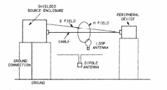
SOURCE: Adapted from Weston, 2001, p. 496.
Typical fields around a cable connected to a piece of equipment placed on a nonconductive table.
Displacement current may flow between the cable and the floor, as well as the ceiling when measurements are made in a shielded room. The additional fields are then an electric field tangential to the cable and a magnetic field in the same plane as the cable.
Electromagnetic Field Measurement in power electronic equipments:
Electromagnetic field measurement in power electronic equipment can be done using a probe, called an electromagnetic field measurement probe. It is connected with an antenna to detect the electromagnetic field and to produce an electrical output. The CPU has its own power supply. To determine the emf of the cpu is the same as measuring the emf of ordinary power supply. The antenna can be connected or placed near the power supply to detect an electromagnetic field. This can be done in the same manner with the other power supply.
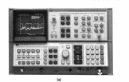
Instrument Theory (all basic information and theory)
Digital Signal Oscilloscope
A digital oscilloscope measures wavelengths. Final output is still analog form – waveshape is visually drawn, not represented by displayed numerical values. A digital oscilloscope uses digital circuitry to prepare the signal for display. In a digital oscilloscope, the analog signal to be monitored is converted into digital form for processing and multiplexing, then it is converted back into an analog image for the final display. (Horn and Darr 1993, p. 18-19)
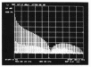
Spectrum Analyzer
Spectrum analyzers are devices that display the magnitude spectrum for periodic signals. These devices are basically radio receivers having a bandpass filter that is swept in time. A spectrum analyzer is essentially a superheterodyne receiver wherein the desired signal is mixed with a swept local oscillator and transferred to a lower, fixed intermediate frequency. However, viewing the device as being simply a bandpass filter swept in time gives a simple understand of the device function.
- spectrum Analyzer.
- its function as swept bandbass filter.
Electric and Magnetic field probes
These are probes used to measure emf in power electronic equipment. An antenna or dielectric is connected in parallel that emits its own emf.
BNC connectors
The Bayonet Neill-Concelman connector, named after their inventors, is also known as BNC, are used as radio frequency connectors. These are used in antennas, radios, and are so effective in low-emission of emf to reduce radio signal interferences.
References
Delton, T. H. and Darr, J., 1993. How To Test Almost Everything Electronic. USA: McGraw-Hill Professional.
Jewett, J. W. and Serway, R. A., 2007. Physics for Scientists and Engineers with Modern Physics. Cengage Learning EMEA 0495112402, 978049511240
Paul, C. R., 2006. Introduction to Electromagnetic Compatibility. John Wiley and Sons. ISBN 0471755001, 9780471755005
Shadowitz, A., 1988. The Electromagnetic field. Courier Dover Publications. ISBN 0486656608, 9780486656601
Weston, D. A., 2001. Electromagnetic Compatibility: Principles and Applications. CRC Press ISBN 0824788893, 9780824788896