Scenario
The college computing requirements are given and a network layout has to be illustrated and described. The college LAN has to be connected to the Super Janet internet network. Therefore the hardware and software requirements for the WAN interface are described.
College computing requirements
Hardware
Main Site:
- Two computer rooms with 20 2.3GHz PCs in each room for student activities.
- 47 2.3 GHz PCs for staff in the college, spread across the college campus.
- 20 PC in the college canteen and coffee area.
- WLAN around the college canteen.
Technology center:
- 30 PC for staff
- 12 stand-alone PC in the office & workshops for CADCAM software.
Software
The software applications that must be accessible from staff computers are: databases, e-mail and websites. The student computers must have virtual classroom software to aid in study, documentation software and connectivity to the internet for research. Secure access to all computer networks must be ensured.
Assumptions
Following assumptions have been made about computer systems in the college campus:
- All personal computers connected to the LAN, WAN run Microsoft Windows 2000 or above operating system.
- Novell NWlink and IBM/NBF are not considered for LAN and WAN configuration and hence NetBIOS over TCP/IP for Microsoft Windows is not described.
- IPv4 addressing is implemented in the college campus.
LAN
The LAN segments in the college campus are:
- Ethernet LAN in computer rooms.
- Ethernet LAN that connects computers in the college canteen and coffee shop.
- WLAN access points around the college canteen and spread across the college campus for the staff.
- Ethernet LAN in the college Technology center.
All LAN segments are connected to the ATM/SONET backbone of Super Janet internet. LAN segments are interconnected through VPN/IP configuration on this WLAN.
Topology
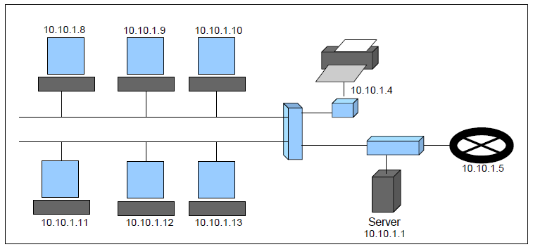
The LAN segments are configured with bus network topology. Both linear and distributed bus technologies are used. All computers connected to the bus receive the data packets transmitted on the network, the packet is accepted by the computer interface with an exact match for the MAC address in the Ethernet frame.
The computers connect to the LAN by 10Base-T twisted copper wire. Hubs and switches are used to lay out network cables in the computer room.

Servers are connected to the switch behind the router gateway.
The routing tables on the LAN router are configured as (example for LAN segment 11.10.1.0):
All hosts on the LAN have the following default configurations:
- Printer IP Address – X.X.X.4
- Default Gateway – X.X.X.5
- Local Server (DNS, RADIUS, e-mail) – X.X.X.1/30 (3 addresses)
Ethernet LAN configuration
The Microsoft Windows operating system on computers connected to the LAN implement IPv4 TCP/IP suite of protocols for networking. The IPv4 LAN networks can be divided into sub networks. The OSI model is illustrated in the figure. The distance vector Routing Information Protocol (RIP) is used for static route configuration on the LAN.
Name Service – Dynamic Host Control Protocol (DHCP) and Domain Name Service (DNS) are used for host and server name resolution.
Session Service – The connection-oriented TCP sessions or connectionless datagram UDP sessions can be established over the LAN.
Error and Network Control – IEEE 802.3 error detection and correction mechanisms are implemented at data link layer and Internet Control Management Protocol (ICMP) is implemented at network layer.
Wireless LAN configuration
WPA2 protocol is used for user authentication by the RADIUS server.
LAN Security.
- Computers – Norton Anti-virus and Norton Internet Security or Microsoft Windows Firewall are installed on the personal computers.
- Wireless Access Points – WAP installed in the college campus have Wi-Fi Protected Access (WPA2) security mechanism. WPA2 authenticates the user and then assigns a dynamic key for wireless data encryption.
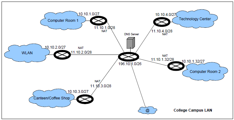
- Routers – NAT is configured on all five LAN gateway routers.
Network Address Translation

Network Address Translation procedure is used to map private IP address to a global IP address in order to hide private IP address or because a private IP address is not a global rout able address. The NAT router saves the private to global address mapping in a NAT table when an external IP packet is sent out by the host with a private address.
WAN
A high-speed ATM/SONET network interconnects all LAN segments in the college campus through a secure Virtual Private Network. A central gateway router on WAN connects all LAN segments to the internet.
Topology
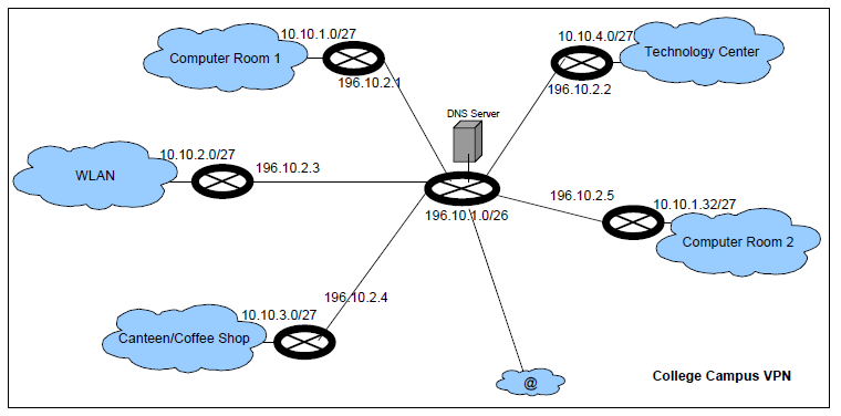
A router gateway provides star network topology for interconnecting all LAN segments. Local DNS server is configured and connected to this router.

The central DNS server is connected behind the WAN router gateway. All requests for domain name resolution are resolved by this server database. If the domain name record is not found in this database and the domain does not belong to the college, the request is sent to the ISP DNS server connected through the external link. The central DNS Server IP address and the WAN gateway router addresses are configured on every LAN segment. The routing table on the WAN gateway router is:
The address 50.10.1.1 is configured as the default gateway address on the WAN gateway router. All internal traffic that reaches the router and has a destination address that is not reachable from any other interface of the router but is a publicly rout able address is sent out on interface 7, otherwise the data packet is dropped. All external traffic that comes to the router on interface 7 is routed to the LAN segment connected to the WAN router or dropped if no address match is found in the routing table. Address 196.10.1.1 is the college campus WAN Gateway Router address that is assigned to the college domain name collegename.org and is present in the DNS record of the ISP (domain name registry where college domain name is registered).
WAN Backbone
All the LAN segments in the college campus are interconnected with a connection to ATM/SONET WAN network. The underground fibre optic cables are laid in the college campus that connect the LAN segments to the campus gateway router.
PVC are configured between WAN Router and LAN routers to distribute the 622.08Mbps internet bandwidth. Bandwidth of 100Mbps is allocated to all the five LAN segments displayed in the picture. ATM is selected as Layer 2 technology to take advantage of the QoS capabilities for traffic configuration.
Janet Internet Network
The telecommunications service provider in the college campus had laid ATM/SONET fibre optic cables that connect the LAN segments and the central office to the internet. OC-12 ATM/SONET link provides bandwidth of upto 622.08Mbps.
VPN Configuration
Virtual Private Network is a virtual network configured over the LAN/WAN network infrastructure. VPN is configured to merge physically separated networks into one single network. The advantage of VPN is that the network resources can be shared and remote access can be provided. VPN connection allows the user to connect to a remote network with an IP address internal to the remote network, thus the user can work on the internal network from a remote location.
The technologies used for VPN configuration are:
- Layer 2 tunnel from VPN Server on the network to the VPN Client on the host or other network that connects to the former. L2TP protocol is used to configure the layer 2 tunnel.
- IPsec – IPsec tunnel is configured between the two endpoints. Authentication Header (AH) or Encapsulating Security Payload (ESP) protocols are used to configure the IPsec tunnel.
- MPLS – Label Switched Path is configured between the VPN Server and the VPN Client.
Private VPN
This VPN interconnects all LAN segments and provides external access to LAN segments. VPN Server runs on the LAN gateway router and VPN client will run on the connecting computer.

A host in Computer Room 1 has to connect to the Technology centre network. This host has been assigned a private address 10.10.4.9 by the Technology centre that can be used to connect to the Technology centre VPN. Host connects to the Computer Room 1 LAN and is assigned an IP address 10.10.1.8. When this host connects to the Technology centre VPN following VPN tunnel routing is done:
Read this table bottom-up.
The <10.10.4.9, 196.10.2.5> header is created for connecting to the VPN Server. The header <10.10.1.8, 196.10.2.5> is added on top of it for routing the packet that is sent to the default gateway address 10.10.1.5 configured on the host.. The LAN router (10.10.1.5) assigns NAT address 11.10.1.8 for this host and replaces the source address in the top most header. Since the destination address is external to the LAN, the packet <11.10.1.8, 196.10.2.5> is sent to the default gateway 11.10.5.1 configured on the LAN router. The WAN router (11.10.5.1) will forward the packet to Technology centre LAN connected on interface 5. Since the destination address 196.10.2.5 is the VPN Server address, this packet is accepted and a tunnel is established to the host 10.10.4.9 after validation of VPN client host address 10.10.4.9.
Public VPN
This VPN connects the campus WAN to the internet.

A VPN tunnel is established between Technology centre LAN and host 10.10.3.8.
Security
The LAN segments are secured by the NAT configuration and firewall on the LAN gateway routers. Access control lists on the router are configured to control the incoming and outgoing TCP/UDP sessions and VPN access. The WAN is protected by NAT configuration on the WAN gateway router for all outgoing sessions. The VPN access list secures the WAN from unauthorized external access. Policies are configured on the WAN router to control access to the LAN segments and servers.
Traffic Analysis
Following network configurations control the traffic on LAN and WAN links:
- Five ATM PVC are configured on the WAN router, each PVC connects one of the five LAN segments to the WAN. The Available Bit Rate (ABR) traffic service is configured on each PVC with peak-cell-rate and sustainable-cell-rate of 100Mbps.
- An unused bandwidth of 100Mbps is available that may be allocated to any LAN segment if required.
- The number of NAT addresses on the WAN routers have been limited to 15 to control the WAN traffic generated from within the LAN. These addresses can be increased if required.
Most traffic is expected to be internal to the LAN. The 10Mbps twisted copper wire Ethernet backbone provides sufficient bandwidth to handle the traffic generated in the busy hour.
The Fast Ethernet 100Mbps fibre optic links may be used to connect the LAN segments to the WAN router. The telecommunications company has laid OC-3 cables to allow for future expansion.
Operations Costs and Budgets
The operating costs of the college campus WLAN are expected for the following resources:
- LAN maintenance – a system administrator is required for every LAN segment, to configure systems, access policies and monitor traffic requirements.
- WAN maintenance – a system administrator is required for the configuration of access policies and traffic monitoring on the WAN, this system administrator will co-ordinate the network maintenance with LAN system administrators.
- Hardware resources – The OC-12 high speed internet link provided by the telecommunications company.
- Hardware maintenance – The maintenance cost for hardware computing resources and software application licenses.
The budget is required for the staff salary, new hardware and software resources, maintenance of hardware and software resources.
References
Metropolitan Area Network Offerings Packet Over SONET, ATM and Gigabit Ethernet. Foundry Networks. Web.
Sprint Technical Report. Sprint. Web.
SriSuresh, P. and Holdrege, M. 1999. IP Network Address Translator (NAT) Terminology and Considerations. IETF. rfc 2663. Web.
Traffic Contract. Wikipedia. Web.
Wilson, D. Mathew. 2002. VPN Tutorial. Web.