Experimental objectives
- Is to forecast the bending moment diagram, collapse load, the number, and the position at which plastic hinges for the portal are formed
- To compare the predicted values with the experimental values found from the experiment and do analysis
- To determine dislocation, failure mode, and not directly member forces in a portal subject to mounting perpendicular and tangential loading
Theoretical Background
Modern engineering plan is founded on the “Elastic Theory of Bending” and the technique is to compute the utmost stresses, which crop up and maintain them in the limit of operational stresses in both tension and compression. These functional stresses are computed from a “factor of safety” and ultimate/yield stress. However, according to Sivakumar(2008), this way of computing is a bit impractical because “Mild Steel Structures do not fail when thew edge Stress of any cross-section reaches the Yield point and will continue to withstand the load as long as the central core of the section remains within the Elastic State”(p. 3).
As the weight on a certain beam is steadily augmented, the maximum stresses will happen at the intense fibers of the most feeble part of the beam. At this state, the exterior fibres are in the plastic state and every raise in weight will lead to substantial enlargement in strain level and consequently deflection at that particular point of the beam. Additionally, rearrangement of stress occurs. At this point, it is presumed stress is invariable in the plastic section. Once the structure achieves a plastic state across the entire cross-section, any additional loading will lead to extreme stress i.e. “enlargement in the curvature at that part and a plastic hinge will be developed” (Romero et al, n.d, p. 3). A single or extra similar hinges are necessary for the total collapse of the structure. The actual number is determined by the kind of structure and if it is, for instance, a supported beam, stiff beam, or a fitted beam. The value or amount of load/weight needed to generate this state is what is known as “The Collapse Load and the ratio of the Collapse Load to the Working Load are called the Load Factor” (Roylance 2000, p. 4). In plastic structure, this feature (factor) is employed as an alternative to the ordinary Factor of Safety.
Assumptions are made in order to be able to compute the bending moment required to generate a “plastic hinge in a specific cross-section and sharing of bending moment alongside the beam at the collapse”(Roylance 2000,p. 5). Some of the assumptions made include: 1) the matter observes Hooke’s Law, 2) the objects are isotropic and uniform in the plastic and elastic states. 3) no ensuing axial force acting on the material, 4) The “cross-section of the beam is symmetrical about an axis through its centroid parallel to plane of bending among others” (Romero et al, n.d, p. 7).
Once force has been applied on a given beam and it is in a ‘partially plastic’ state, any further increase in the load will lead to further enlargement of zones deepness, and, it is presumed that plastic elastic can take place at yield stress leading to two stress wedges i.e. compression and tension regions. The plastic region takes up the entire cross-section area and is explained as having achieved a ‘fully plastic’ state. Once in a fully plastic state, any further increase at the moment leads to “member to act as if hinged at the neutral axis and this is called a plastic hinge and the bending moment that leads to the generation of a ‘plastic hinge’ is called the ‘full plastic moment’ and is represented by ‘Mp’” (Roylance 2000, p. 8).
Plastic pivots or hinges are formed because of bending or twisting in a configuration member at which an infinite rotary motion can occur at a stable Plastic Moment at that given section. So long as there are a number of positions of “local” utmost bending/twisting moment alongside the portal frame or beam there are a number of points of “local” greatest Bending Moment along the beam, the first Plastic Hinge will be generated at the numerical greatest point provided working load stipulations are still under operation(Gere & Timoshenko 1990, p. 328). If additional Plastic Hinges are needed for cave-in or collapse of the frame, then it will take place at the subsequent lesser value selected from the remaining neighboring maxima. As soon as adequate plastic hinges have been generated to switch the structure/arrangement into a mechanism then the collapse of the entire structure will take place. The actual number of Plastic hinges required for breakdown does not change for a specific structure depending on the set loading circumstance, even though a section of the beam may collapse separately by the generation of a slight number of hinges. The structure acts like a hinged mechanism leading to rotation of neighboring hinges in contradictory directions structure. In short, the collapse or ultimate weight/load is achieved when a mechanism is produced. The actual number of plastic pivots generated due to weight applied on the frame or any beam should be just enough to create a mechanism (Gere & Timoshenko 1990, p. 340).
Results
The experiment was performed and results were recorded in the excel sheet as below:
Discussion
Calculations
- From the data obtained during the experiment, we can determine the ultimate load according to the following procedure: since this is a simply supported beam, a single point of highest Bending Moment and the collapse state will be achieved when a Plastic Hinge is generated at this specific point.
Maximum Bending Moment is given by=Wab/I under the load

Since we have a single plastic hinge, the Bending Moment at hinge WC=MpXI/ab
Using the equation My/Mw = Fy/Fw and Mp=S (Fy/Fw) Mw and making simpler the equation we see that Maximum Bending Moment=S ( (Fy/Fw)W). We can now determine the ultimate load as plastic moment= 8Nm and yield stress= 246Mpa while cross-section areas= 12.7mm by 3.2mm
Ultimate load,Wy/2X 5= (3.2 X 12.72/6) 246
Ultimate load, Wy= 8.464 and the loading ratio=H/V=105/210=0.5
- Collapse mechanism, number, and position of hinges: To comprehend how the collapse mechanism occurs, a clear understanding of plastic hinges is necessary. A plastic hinge is formed as a result of bending or twisting in a structural/configuration member at which an unlimited rotary motion can occur at a steady Plastic Moment at that given region. Provided there are several positions of “local” utmost bending/twisting moment alongside the beam there are a number of points of “local” greatest Bending Moment along the beam, the first Plastic Hinge will be generated at the numerical greatest point provided working load stipulations are still under operation. If additional Plastic Hinges are needed to cave in, then they will take place at the subsequent lesser value selected from the remaining neighboring maxima. As soon as adequate plastic hinges have been generated to switch the structure/arrangement into a mechanism then the collapse of the entire structure will take place. The actual number of Plastic hinges required for breakdown does not change for a specific structure depending on the set loading circumstance, even though a section of the beam may collapse separately by the generation of the slight number of hinges. The structure acts like a hinged mechanism leading to rotation of neighboring hinges in contradictory directions structure. The collapse or ultimate weight/load is achieved when a mechanism is produced. The actual number of plastic pivots generated due to weight applied on the frame or any beam should be just enough to create a mechanism, which in this case mechanism occurs after three hinges are formed at different positions.
- Static check: in a portal, a frame as shown in the diagram below, has stiff joints therefore, when the load is varied, locations of greatest Bending Moment will take place at the joints. In a cave-in, a few or every joint will be converted into Plastic Hinges. The figures below are the bending moment that illustrates the possible mechanism of collapse under loading conditions. Theoretically, the structure has a span of 1 and has an elevation of H. A weight of V is applied at the center (vertical load) and horizontal weight of H. Under these circumstances, Plastic Hinges may be generated in any arrangement at locations A B C D, and E.
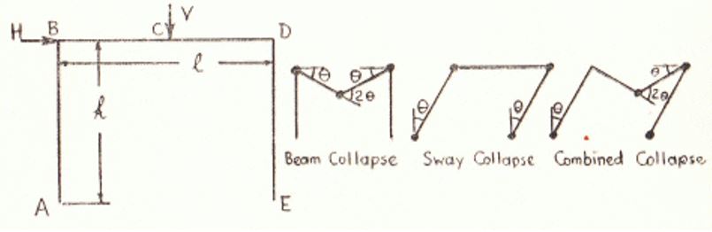
(Source: Codecogs Engineering 2010, p. 7)

A breakdown state will occur when adequate hinges are generated to form a “mechanism.” The possible three ways of collapse mechanism include:
- The portal frame cave in with hinges at positions B, C, and D
- swing disintegration with hinges at positions A, B, D, and E
- joint fall down with turning points at locations A,C, D, and E
- Plotting of bending moment diagram: from the results obtained as indicated in the excel sheet, the following bending moment diagram is generated. First, we must compute the bending moment at different locations on the beam. This is given by the formula, Bending Moment, M=” Force x distance between the location of application of force and the location at which we want to compute bending moment” (Turchetto 2009, p. 4). Taking horizontal displacement and force, we calculate bending moments as below. The degree of consecutive shear ordinates augmented and therefore the gradient of the bending moment graph is positive since the graph is approaching the vertical axis. Unexpected alterations in the shear figure produced unexpected alterations in the gradient of the bending moment curve. Intense moments create perpendicular lines in the bending moment arc.
- For this portal frame, after the first hinge was formed, two more hinges were formed. From the structure in section C, when a weight of V is applied at the center (vertical load) and horizontal weight of H. Under these circumstances, Plastic Hinges may be generated in any arrangement at locations A B C D, and E. A horizontal weight applied on the frame will lead to sway cave in with rotations angle θ taking place at points D and B. while for vertical load, the rotary motion of angle θ occurs at points D and B. Finally, the third hinge is due to a combined weight where there is no rotary motion location B, and cave in will lead to the generation of plastic hinges at positions C and D.
- From the results, we see that theoretical and experimental are related with small deviations. These deviations are a result of assumptions made for example that the beam will behave ideally and obey Hooke’s Law. This is not practically true. Those assumptions are the basis of deviation. Hypothetically, the plastic pivots are presupposed to shape at positions at which plastic rotary motions take place. Consequently, the measurement lengthwise of a plastic hinge is deemed as zero. Practical, the ultimate load was found out to be 8.464Nm while the theoretical one as 8Nm. We have a difference of 0.464, which can be attributed to both experimental error and assumptions made while experimenting. Percentage error is given by the following calculations: percentage error=0.464X100/8=5.8%. This is well within the acceptable deviation range. Sources of error could have mainly resulted due to inaccurate measurements and also wrong positioning of the load on the portal frame. Finally, an error will occur if the meter is not properly zeroed.
Conclusion
The experiment was carried and from the results obtained, the bending moment diagram, collapse load, the number, and the position at which plastic hinges for the portal are formed were determined. The number of plastic hinges formed that led to the collapse of the portal frame was found to be three. The collapse load was achieved when a mechanism was produced as a result of varying the load both vertical and horizontally. The actual number of plastic pivots generated due to weight applied on the frame or any beam should be just enough to create a mechanism, which in this case mechanism occurred after three hinges are formed at different positions. This agrees with the theoretically predicted number of plastic hinges.
Further, we see the objectives of the experiment being achieved where the experimental value and practical values were compared. In theory, the plastic moment was 8Nm but practical, it was found out to be 8.464Nm. The percentage error was found to be 5.8 percent. This is well within the acceptable deviation range. Sources of error could have mainly resulted due to inaccurate measurements and wrong positioning of the load on the portal frame. From the experiment, the dislocation, collapse mode, and not directly member forces in a portal subject to mounting perpendicular and tangential loading were examined and the diagram plotted. Therefore the objectives of the experiment were met.
List of References
Codecogs Engineering 2010, Plastic theory of bending, Prentice Hall, New York.
Gere, J & Timoshenko, S 1990, Mechanics of materials, Wakefield Pres, Kent Town.
Romero, J, Mappa, P, Herskovits, J & Mota-Soares, C 2003, Optimal truss design including plastic collapse constraints, Institute Superior Techno Journal, vol. 3, no.1, pp.1-8.
Sivakumar, MS 2008, Strengths of materials, Indian Institute of Technology Madras Journal, vol. 12, no. 2, pp.1-20.
Roylance, D 2000, Statics of Bending: Shear and Bending Moment Diagrams, Massachusetts Institute of Technology Physics Journal, vol. 230, no 30, pp. 1-12.