Abstract
The system analysis, development, and implementation phases reflect a framework that the system analyst used to design the order processing system that could be implemented to solve various problems related to the existing system. The rationale was to automate the order processing system to optimise on the computing processing capabilities of information systems. The benefits include fast, reliable, and accurate transformation of data.
The problems with the existing system were inaccurate order processing, lack of unique capabilities such as web-based presence besides poor inventory management, and lack of reliance on manual operations. To start the process, the problem with the existing system were analysed and solutions were proposed that could use an information system with interactive features that could enable users to interact with the system effectively.
A business profile was written, use-case diagrams developed, structured English written to represent various system development activities. Entity relationship diagrams, activity, and class diagrams were also developed. The system objects, which include and their table attributes defined and normalized into 3N to show the unique relationship among the system entities. The data flow diagrams and entity relationship diagrams were used to show how the system could be coded using any programming language. The resulting system consisted of various components that could interact at different levels to fulfill the system development objectives.
Issues with Order Processing System
The transaction processing system in the case study consists of various components, which include the business event or transaction component, the detailed report system, the transaction processing system, and the organization’s database (Shelly & Rosenblatt, 2010). For each of the components, there are specific sections that constitute the system, which include the supermarket’s central warehouse for the storage of different products.
A critical analysis of the system shows that the main elements used to define the order processing system are grouped into there:
The entity purchasing a product (customer)
- The purchasing department
- The supplier of products,
- Hardware on which the software runs,
- Application software that runs on the underlying hardware and operating system
- Data that is used for decision making, and
- Processes to ensure that the transactions are fully committed
- Hardware: computer, monitor, printer, and other peripheral devices.
- Software: Application software for data processing
- Data: Consist of objects such as input data for processing customer requests, output data for processing
- Database: The database object consists of a collection of tables that consist of rows and columns that are connected to each other through primary and secondary keys. Rows are uniquely identified using primary keys.
Team members
A team was constituted consisting of different members. It was decided that members who performed special roles were recruited into the team to be part as depicted below.
System analysts
The role of the system analyst was to ensure that identify the system requirements, hardware and software requirements, examine the existing business models and IT systems, test feasibility of the system, implement, configure, and recommended the system for use. The characteristics of the system analyst were strong analytical and interpersonal skills, which enabled him to work at the individual and organizational levels in performing the assigned duties.
Team leader
The leader was to provide the guidelines necessary for the system development team to work as a team, identify the skills necessary for the team to work effectively, provide training and development programs, and identify areas of improvement besides guiding the team work through the system development life cycle.
Business profile and purpose
The business profile is a descriptive document that shows the details of the transactions done to fulfill the business objectives of the business organization. The system will provide the company with the capabilities to perform order processing on a computerized platform.
Company name
XLC transaction processing Inc
The Idea
The Company was focus on the provision of order processing based on a monitoring the supply of goods to ensure inventory levels were accurate and replenishment of products could be done on time.
Purpose
The purpose was to develop a transaction processing system that could be used for inventory warehouse management. The system could be used to record transactions in the supply chain system of the supermarket chain.
Business model
The system could include both web-based and brick and motor selling and buying methods, but the order processing activities could be based on the information system.
Problem
A critical analysis of the situation showed that the existing system has serious weaknesses that made it difficult to reconcile the inventory at different stock levels. It was noted that the existing system could not capture all details of all transactions besides failing to capture and reconcile departmental level transactions that occur at the departmental levels. In addition, the existing system uses manual methods to record the balance of products in store. However, that makes it difficult to accurately determine the stock levels to determine when the stock should be replenished.
Issues IT/IS can address
According to Amato, Ariola and Cosentino (2010), the IT/IS could be used to address the above problems by providing a platform that consists of an underlying hardware on which software runs to perform the various functions in an automated manner. In this case, the system consists of web-based modules that enable real time communication between the management and the customer and to track other activities such as providing information on inventory levels and the necessary level of replenishment to be done. In addition, different modules that perform different functions were developed and integrated into a single system with different function.
In summary, the benefits of the resulting information system could be the automation of the order processing activities, effective monitoring and replenishment of the stock levels, accurate inventory, and a wider market reach using the Internet. Besides, it could make it possible to work remotely and enables speedy access and retrieval of information from anywhere.
Anticipated Improvements
Because of the various problems that include failure to capture inventory information in real-time, functioning as a standalone application, and lack of a web presence, it was justifiable to develop a new system that could provide solutions to the problems highlighted as being inherent in the existing information system.
Solation
The proposed solution to the problem was to develop a system consisting of different features with an interface that could enable users from different backgrounds to interact with the system. Information technology came in handy by providing the right platforms to develop the system that could enable users to conduct their transactions accurately. Among the proposed features were:
- The Web Ordering System
- Menu Management System
- Order Retrieval component
- Order entry form
- Inquiry form
- Payment form
The expected benefits of using the new system include:
- Better communication
- Easy order placement
- Easy to compare prices
- Better inventory management
- Easy communication among the departments
- Saving time and labour
- Easy report generation
Use case diagrams
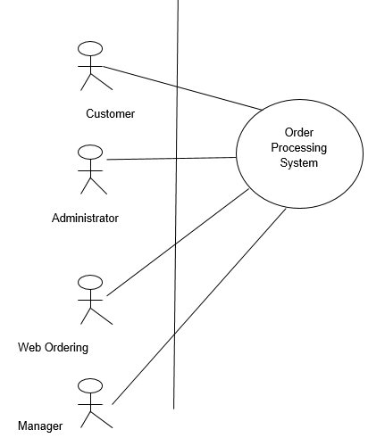
Deception
It is evident from the use case diagram shown above that the customer interacts with the web-based system and collects all the information about the items in store. The customer in this case is the owner of the business who uses the order processing system to order for items and replenish their stock to keep the stock levels as required. Figure 1 shows the system actors such as the manager who is responsible for carrying out the managerial activities necessary to ensure that the business transactions are done efficiently (Hoffer, 2012).
In addition, the manager has the overall responsibility of ensuring that all activities are done according to the laid down business rules (Diniz, Da Silva, & Netto, 2010). On the other hand, the figure shows the next actor to be the systems administrator who is responsible for keeping the system up and running to ensure that it does not incur errors and other associated problems.
Case specification
The system is further decomposed into the following components
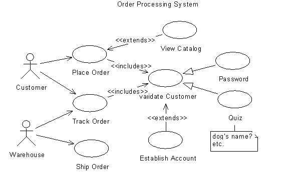
It is evident from the above diagram that the use case diagram consists of decomposed roles and activities for each actor in the system. The system shows how the customer interacts with the system that is also the main object. The customer interacts with the system by placing an order and tracking the tracking the order using the order processing system (Duan, 2010). Here, when creating tables, it is crucial to note the relationships with the warehouse, the ship and orders that are to be shipped. Here, the uniqueness of the system is that there is a link between the customer, the ship order, the warehouse, and the order attributes.
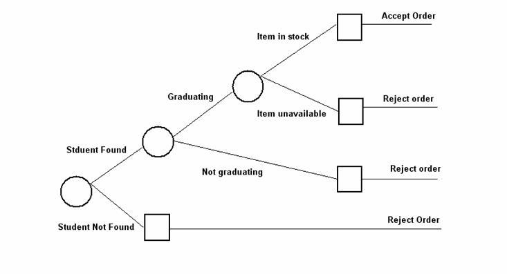
The decision tree
On the other hand, it is evident that the customer has a link or relationship with the catalogue because, when the order is placed, the customer is free to view the catalogue before confirming the order. On the other hand, the customer cannot complete the transaction without creating an online account that is valid. Once it has been validated, the customer is free to make orders on the order processing system.
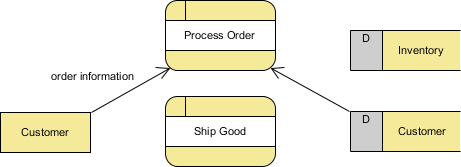
Figure 4 is an overview of the decomposed components of the system as they have been designed. Here, a summary of the system shows how different objects interact with the system. Here, the inventory, customer, and transaction are all related with the system. On the other hand, the system component for order processing is the one that connects the customer and order processing element.
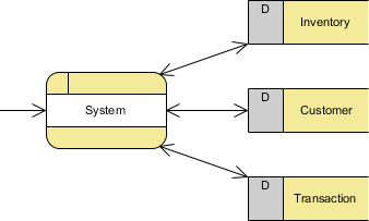
The customer and inventory are related in such a way that once the processing is complete, the order can be confirmed and shipped to the customer.
Structured English
- Confirm whether customer has an account
- If there is no account
- Then customer can open account
- Else
- If customer has no account
- Then customer can open an online account
- If customer account is active
- Then customer can place an order
- If manager sees customer orders
- Then manager can verify if customer requests can be fulfilled
- If customer orders cannot be fulfilled
- Then manager orders for more products into the store
- Else manager sanctions the items to be sent to the customer
- Once order is confirmed
- System generates amount to pay’
- Customer confirms order
- Customer pays
- System acknowledges order
- System records customer information
- Order sent
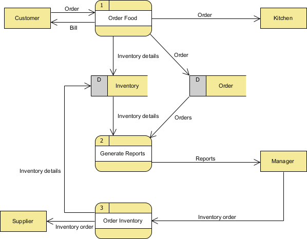
The diagram below shows the data dictionary.
Commentary
The above diagram shows the relationship between the supplier and the manager of the company and the relationship among system entities. An example is to supply a hotel with food items from the supermarket. The customer might place an order for a certain meal that should be prepared using various components that are supplied to the hotel. The manager of the company takes the responsibility of ensuring that the system inventory generates stock in store and if the items are in stock, the customer can be allowed to complete the order.
System ERD
The entity relationship diagram shows the relationship between different system components.
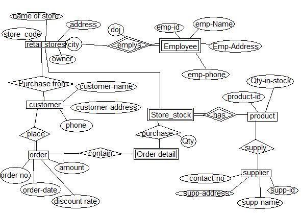
As per the requirements of meeting the specifications of the 3N form, it is evident form the above ERD that each entity has a relationship that has been decomposed into the third normal form. The entities in the system include the customer, supplier of items, shipment, items, order requests, and suppliers. In the system, it is important to note that the supplier provides goods to the customer. The customer submits the order to the supplier who confirms that the order has been placed and paid for. Here, the rationale for normalizing information into the 3N form is to ensure that the relationships are not redundant and update and deletion anomalies do not occur.
Relationships and attributes
- Customer = [Inquires about product, places order, buys product,
- confirms payment, connects with system]
- Supplier = [with customer, manager, system}
- Shipment = [supplier, manager, organization]
- Name of store = [store code, name, and address]
- Relationship in the 3 Normal forms is shown below.
- Retail store (Purchase form, store stock, employees, products)
- Purchase form (Products, customer, place, phone, order)
- Order (Order_no, order date, order discount)
- Products (Order no, contact no, supplier, quantity in stock)
- Customer (Phone, place, amount, order)
- Supply (contact no, supplier, supplier address)
Data dictionary
Based on the processes shown in figure 7, it was possible to note certain points, which include the functions and components of the ERD. Each entity on the relationship has attributes or unique characteristics that are used to model the system. The attributes in figure 8 can be composite to make it possible for the the entities in the system to be decomposed further.
On the other hand, it was possible to see that different entities have different attributes and each attribute has unique values. The relationship can be a one-to-many, one-to-one, and many-to-one relationships. In each case, there were noted some instances of inheritance, generalization, and specialization.
On the other hand, the data dictionary provides the storage of data and description of the data in store. Different fields were created in the data dictionary and those that are unique provide the unique key necessary to for data access and retrieval. All data items have at least a unique attribute or unique attributes. The data dictionary in figure 8 provides the details of all the system transactions and other events that are done on the system to ensure successful fulfillment of the system objectives.
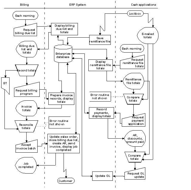
As shown in the diagram below, the system activity diagram shows the entities and the activities that are done by each entity. The system shows the activities such as order checking on the order processing system, and the responses from the system (Kendall & Kendall, 2010). When the order checking is done, the procedure involves doing a look up for the item, and if the item is available in store, then the customer confirms and makes the order. Once the system has accepted the order, the management views the order and produces a summary of the order.
System activity diagram
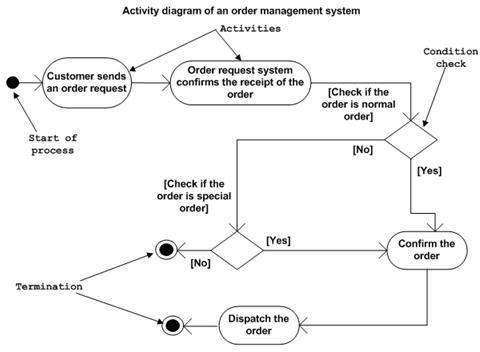
After the system has accepted the order, the management reviews the order before making an update of the order inventory. On the other hand, the customer interacts with the system to confirm that the order is correct. Because the order processing system is web-based, the following actions can be done on the system. Additional activities that are done on the system include creating a customer account, managing the account, logging into the system, navigating on the site to select the required items, selecting the items, reviewing the order, and placing the order. The goal of the order processing system is to enable the customers place orders and confirm the placement through the order processing information system.
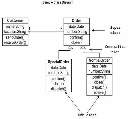
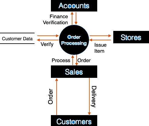
On the other hand, the system consists of the static components that show the system entities as depicted on figure 9. The order processing system enables activities such as updating vendors on the system, adding items, creating categories on the system, deleting and adding items, and confirming the placement of orders and items on the system. The system also performs other activities such as retrieving orders, displaying the orders in a form, and making the orders to be processed. Figure 10 shows one of the components of the data flow diagram within the system and the system entities and how the interactions among the entities happen. It is important to note that various modules interact within the system. Here, the different modules include the condition, control, loop, and jump components.
DFD
The data flow diagram shows the flow of data within the system and the processes that enable the processes to be done.
Final report
It is important to note that the system analysis, design, and implementation methodology were process intensive. There were several points that were noted as each deliverable was achieved. As mentioned in several steps, one can note that the process begins with problem identification and requirements investigation. Here, each of the components of the order processing system was investigated in terms of the functionality and the relationship among the components.
Here, the system analysis phase enabled the system analyst to determine the weaknesses of the existing system and the expected areas to improve on. Besides that, developing an effective system that fulfills the goal of the desired system, the system analyst deemed it is necessary to create a skilled team to perform various roles necessary for developing the system. In addition, the roles of all team members were clearly defined. Here, the key team members were the manager, the system analyst, programmer among others.
It was necessary to note the importance of using various tools to model the system at different levels and for different purposes. One of the learning points was the use of data flow diagrams to model the flow of data within the system and the components for creating the data flow diagram. The flow of data can either be logical or physical. Structured English was another tool that was used to model the system. Structured English provides a description of what is required to write the program code to run the system.
References
Amato, F., Ariola, M., & Cosentino, C. (2010). Finite-time control of discrete-time linear systems: analysis and design conditions. Automatica, 46(5), 919-924.
Diniz, P. S., Da Silva, E. A., & Netto, S. L. (2010). Digital signal processing: system analysis and design. New York: Cambridge University Press.
Duan, G. R. (2010). Analysis and design of descriptor linear systems (Vol. 23). Springer New York: Science & Business Media.
Hoffer, J. A. (2012). Modern Systems Analysis and Design, 6/e. New York: Pearson Education
Kendall, K. E., & Kendall, J. E. (2010). Systems analysis and design. New York: Prentice Hall Press.
Shelly, G., & Rosenblatt, H. J. (2010). Systems Analysis and Design, Video Enhanced. London: Cengage Learning.