Introduction
Computer Numerical Control – CNC machines have become very popular in the past few days since they offer acceptable reputability of the machined parameters, allows many operations to be combined, allows machining in more than three axes, carries out the process with very little human intervention and a single operator can operate many machines. The paper provides an in-depth analysis of CNC machines and automated machining.
Characteristics of CNC Machines
A CNC machine, depending on the type may have two or more axis that can be controlled by a computer program. A CNC machine is defined as “A system in which the actions are controlled by direct insertion of data and the system must automatically interpret and carry out the instructions”. A dedicated computer is built into the control system of the machine and is connected to the servo controllers that provide motion to the machine axes. Based on the program written in G Codes, the axis would move to the new position at the required feed while the machine spindle would rotate at the specified cutting speed. Depending on the type of machine, the turret may have a number of tools that are fixed in special tool holders, and the distance from the tooltip to the spindle seating face is entered into the computer and this is called pre-setting.
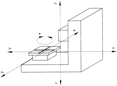
This distance is called the offset and the spindly axis will move back or forward to ensure that only the tooltip, tool sides are in contact with the faces to be machined. A CNC machine would have multiple programmable axes such as X, Y, and Z and in addition, the machine table which can be programmed to turn so that a fresh face is presented when required. By using proper tooling and design and depending on the number of setups required, it is possible to load more than one component on the different faces of the tooling. The machines can have two fixtures, one that is inside the machine with components and undergoing machines and the other outside so that un-machined components can be loaded and kept ready for the next cycle so that idle time is kept to a minimum (Pabla, 2007).
CNC machines can also be integrated with CAD and CAM processes and it is possible to convert a CAD design into a programmable set of instructions so that the required dimensions can be machined.
Primary processes and their characteristics
CNC machines can be used for performing a number of operations such as milling, drilling, boring, tapping, reaming, spot facing, turning, EDM, grinding, and so on. Materials that can be machined include castings, forgings, bar stock material, roughing operations for dies and molds, stamping, drawing, plastic and wood components for prototyping, and so on. When it comes to CNC machines there is a different class of machines and these are designated as per the machining operations that they can carry out. The different primary processes are grinding, drilling, boring, milling, turning, EDM, drilling/ boring and tapping, metal spinning, deep drawing, and others. The different primary processes and the machine types are given in this section (Smid, 2005).
CNC Turning
CNC Turning machines are special types of lathes that are used to turn stock material, castings of odd shapes, forgings, and other components. These machines have a rotating spindle that can be made to rotate at different surface speeds. A turret is placed at the back and it can have multiple tool holders that are used for turning off the external and internal diameters, internal and external threading, fine boring, internal grooving, circlip machining, taper turning, and others. The machines are limited by the maximum dimension and weight of the component. Maximum size refers to the maximum swing over the bed that can be accommodated and the component has to swing clear of the bed while rotating so that the component does not dash against the bed while rotating. Other factors to be considered are the maximum stock to be removed, the number of tools required in one setup, tooling required, and so on. Cutting tools that are used include carbide inserts, cermets, HSS tools, and diamond insert tools that can only be used for nonferrous machining (Stephen, 2008). The following figure shows the layout of a typical CNC lathe.
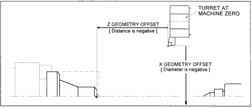
While machining longer components such as rods and bars, a dead center, as shown left side should be used as this gives proper support for the job and reduces problems of overhang. Threading of different forms such as metric, inch, NPTF, and others can be cut and the required pitch can be maintained. These machines come equipped with coolant so that the machined component can be cooled and the burr can be removed. By using rigid work holding devices, complex-shaped parts such as castings, small housings can be machined for the bore, internal and external circlip grooves, and other geometries. Typically components such as shafts, propeller shafts, driveshafts, pulleys and others can be machined. There would essentially be two setups since the side that is clamped in the spindle would have to be reversed and machined in the second setup (Stephen, 2008).
CNC Milling and Machining Centres
CNC milling and machining centers are the workhorses of the manufacturing industry and are used to perform a number of operations. The main types of CNC machining centers are horizontal and vertical. While CNC milling is used to perform only milling operations, CNC machining centers perform a number of operations such as milling, drilling, boring, internal threading, slot milling, and many others. The machines are used to combine many operations and drastically reduce the setup time. They are most useful when the parts require complicated tooling, different faces have to be machined in the same setup, different bores need to be aligned with a common reference point, and when the requirement is for a medium output. Since these machines have a central table on which the component can be clamped, it is possible to machine all the faces by just reloading the component so that different faces are exposed.
It is essential that clamping must be done on a flat surface of the component and that the required master dowel holes are machined so that subsequent operations take the location of these master dowels. The machines have an automatic tool changer in which a number of tool holders and qualified tools can be placed. The tool holders are designated with numbers such as T1, T2, and so on and the required tool can be called in the CNC program. A tool changer is used to remove the tool from the spindle and load a new tool as per the requirement. By employing appropriate G codes for the program, it is possible to carry out canned cycles, peck drilling, contour milling, and even cam lobe milling.
While three axes machines are common, machines with 5 axes are also available. Some manufacturers also offer very high precision machines for jig boring operations that are used in tool rooms for the manufacture of jigs and fixtures, dies and molds, and other precision parts. Internal threads are cut using taps of the required pitch and thread diameters and special tapping attachments need to be used. In tapping, the tap is fed as per the required feed rate while rotating clockwise, stops at the end of the stroke, and then rotates anticlockwise and retracts the tap to produce a fully finished thread. The machines can be used for machining of castings, housings such as crankcase, gearbox, fuel pumps, governor housing, water pump casing, flywheel housing, gear case cover, cylinder block, and cylinder head, and many others (Bannister, 2006).
Rotary Tables
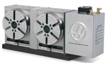
Rotary tables are a key component of the CNC machining center and jigs and fixtures, as well as components, can be clamped on them so that machining can be done. The devices are classified as per the table size, the weight they can accommodate, type of servomotor used, number of indexing possible, and mounting diameter. The tables are provided with a flat face that is hand-scraped for perfect flatness and very low face run out. Machines with the tiltable axis are also available and these can be used for machining inclined and angular holes and faces. Depending on the type of machine and control, the table can be either programmed to index at a rapid rate to the required rotation angle or it can have a programmable ax so that the table can be given a feed when it is rotating and this facility is used to mill cam lobes (HAAS, 2008).
Work Holding Devices
CNC fixtures are usually of modular design and allow additional elements to be added or replaced as per the component requirements. The following table shows the types of fixtures used for CNC machining centers.
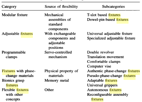
The fixtures need to have a master locating dowel so that the component can be seated accurately and the dowel pins also serve as the reference point for the machining program. The fixtures should be rigid enough to withstand the severe vibrations from the machining process and the clamping should not cause the component to be distorted.
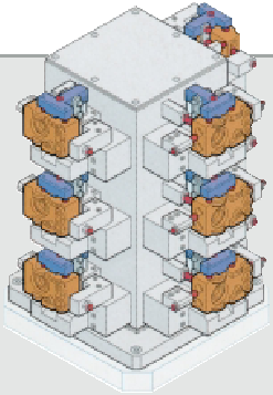
A modular fixture with multiple tools is shown below.
Tooling
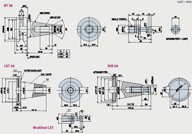
Tool Holders play a very critical role in the accurate machining of components. The tool holders have an ISO or a Morse taper on the outside and these are pushed into the machine spindle by the tool changer. Locking lugs at the sides prevent the tool holder from rotating or getting dislodged in the spindle. A locking stud at the back helps the tool holder to be locked into position during machining. The tool shank can be pushed into the tool holder and a tang ensures that the tool remains firmly seated in the tool holder. Different types of tool holders are available as per the tool diameter, spindle taper size, and others. For a specific machine, since the spindle size is fixed, all the tool holders would need to have the same external taper. The following diagram gives an illustration of different tool holders.
Spindle Power
Spindle power defines the power of the machine and specifies the maximum amount of material that can be removed, the maximum size of the tool holder, and the machining parameters that can be used. The spindle power is specified by the maximum speed in revolutions per minute and the power expressed in kilowatts and the power is a direct function of the servo motor that is used to drive the spindle. The following graph shows the performance of the machine with reference to the spindle speed, torque, and power output.
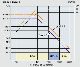
In the graph, it can be seen that as the speed increased, the available power would increase but the torque would reduce. For this reason, when using heavy milling cutters or when the depth of cut is more, lower speeds are used.
Machine specifications of a typical CNC machine
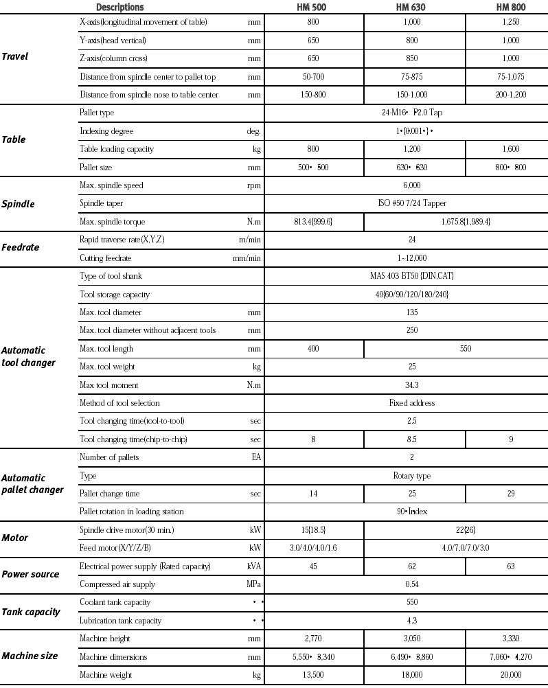
While there are many parameters that are used for specifying a CNC machine, some important parameters to be used include the table size, the maximum size of the component, number of axes, spindle power and speeds, number of tools available in the tool magazine, the maximum size of the tool and so on. The following table gives a typical specification for a CNC machine.
Market Analysis
The CNC market is projected to be worth more than 5000 million dollars and the global demand varies with the economies of different areas. Countries such as India and China that have seen increased outsourcing of components from the US and Europe show an increase in demand. Please refer to the following graph that shows the trend.
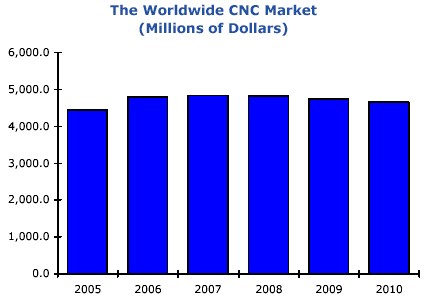
The report by the ARC advisory group suggests that many leading manufacturers such as Dixie, HAAS, Traub, Vomard, Makino, BFW, HMT, and others provide customized services that address the needs of the low end and low cost to high cost and high precision machines.
Conclusion
The paper has analyzed different types of CNC machines and conducted an in-depth study of tooling, work holding devices, spindle power, and other parameters for the CNC machining centers.
References
ARC. 2008. CNC Worldwide outlook. Web.
Bannister Ken. 2006. Programming of CNC Machines: Student Workbook 2 edition. Industrial Press, Inc. ISBN-13: 978-0831131623.
Doosan. 2008. Doosan Infracore Machine Tools. Web.
HAAS. 2008. Rotary Indexing Table. Web.
Hayden David. 1997. 7 Easy Steps to CNC Programming. A Beginner’s Guide. Haydenpub.Com; Spi edition. ISBN-13: 978-0970530905.
Madison James. 1996. CNC Machining Handbook: Basic Theory, Production Data, and Machining Procedures. Industrial Press, Inc. ISBN-13: 978-0831130640.
Pabla, B.S. 2007. CNC Machines. New Age International Publications. ISBN : 978-81-224-2019-7.
Rong Yiming. 1999. Computer-Aided Fixture Design: Manufacturing Engineering and Materials Processing Series/55 (Manufacturing Engineering and Materials Processing). CRC Publications. ISBN-13: 978-0824799618.
Smid Peter. December 20, 2005. CNC Programming Handbook, 2nd Edition. Industrial Press Inc. ISBN-13: 978-0831131586.
Stephen. 2008. Factory automation: Siemens equips Kia Motors first European factory. Web.