Abstract
This paper delves deep and wide on the contemplation themes associated with SERDES jitter. To begin with it presents a straightforward structure perception for important successive information connections (physical layer). Fundamental jitter illustrations are defined as well as hypothesis required to comprehend the roll of the SERDES compounds in statistics linkage concert. First categorize replica to assist a comprehension of the association flanking jitter and bit-error-rate is illustrated. Critical SERDES jitter characterization precincts and measurement approaches employed by Lattice are described and conversed. Certain approaches concerning SERDES blue print and superior jitter presentation are also granted, William Stallings (2000:120-34).
Introduction
The advantages of employing high-speed serial statistical connection across PCBs as well as on the backplanes have become quite apparent to apparatus and structure designers. An increasing application of ASICs and coded ICs offer interlinked SERDES framework. The figure 1 below indicates a classical elevated speed serial statistical connection employing SERDES, William Stallings (2000:120-34).
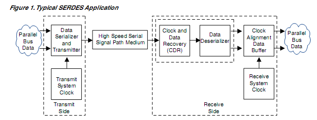
Its function is too speedily transmit statistics from a corporeal region to another. The statistics, normally in parallel bus form, is sequential to a particular prominent speed indicator. The indicator is relayed across the medium orbit that is obviously a superior excellence communication line path to the new region. Associated in the SERializer as well as DESerializer functions are integrated timer-recovery circuitries, required to generate an elevated-speed serial arithmetical pathway. The pathway might be along a printed circuit board (PCB), a backplane with myriad PCBs, or through cabling connected to a succeeding equipment shelf. On the receive end of the path, a chronometer and statistical resurgence circuit receives the signal and extracts a fittingly manned bit chronometer from the statistical flow. The statistical indicator is then deserialized down to a lower tempo parallel statistics framework. The parallel statistics is aligned with the chronometer to the remote system timer. Characteristically this has is done by using a two fold port FIFO memory buffer. This presents an effective solution to the intricate monitoring anomalies related with transmitting towering bandwidth statistics across PCB, backplanes as well as apparatus frames, William Stallings (2000:120-34).
This presents a successful solution to the complex timing anomalies associated with transmitting elevated bandwidth information transversely PCB, backplanes and even gadget frameworks. As this cluster item progresses with enhancing speed and density, so does the significance of comprehending the jitter attributes as well as cons of the SERDES elevated speed serial crossing point, William Stallings (2000:120-34).
Jitter Rudiments
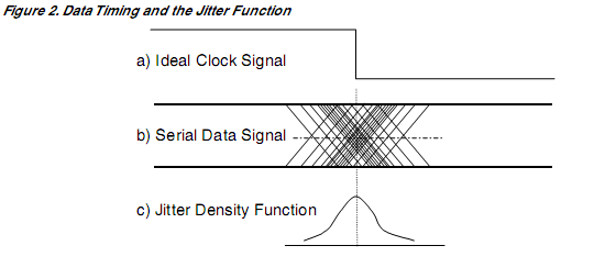
In simple terms jitter can be unambiguous as the moment in time error of a digital suggestion. Most digital indicators have standard era intermissions at which echelon conversion can happen. When a digital indicator waveform is related to the actual interlude clock waveform, as shown in figure 2 below, Abbott H.H (2004:20-39).
Types of Jitter
When handling jitter in the actual arrangement, it is frequently constructive to cubbyhole diverse forms of jitter that can happen. This procedure normally helps recognize the core basis of challenging jitter. The composite jitter connected with statistical indicators is known as holistic jitter (TJ). TJ might be thought of as composite function, composed of various diverse components emerging from diverse noise as well as indicator origins within the structure. The jitter mechanism is collectively classified into two main groupings: deterministic jitter (DJ) as well as random jitter (RJ). In any case the Jitter compounds are not truly indiscriminate in the information sense and therefore engaged as deterministic jitter (DJ), Abbott H.H (2004:20-39).
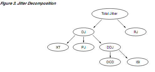
Deterministic jitter components can be clustered into definite shapes, consisting of periodic (PJ), inter-symbol interface (ISI), obligation sequence deformation (DCD), and cross talk (XT). Discussing these jitter mechanisms as well as their plausible foundations with a configuration tracks. Cyclic jitter is generally initiated by chronometer and transporter indicators within apparatus. Classically asynchronous chronometers of practically any occurrence can be reprobate. Their regularity machineries coupled into statistical indicators paths and apparatus. On a bigger scale, discrepancy statistical indicator paths as well as interconnections achieve these interlude elements as regular mode indicators and disallow these periodic elements. Non-linear state of semiconductor gadgets nevertheless enhances some state of indicator incorporating to happen, normally at the differential line recipient. The outcome is indicator inter-modulation that translates to added arithmetical indicator jitter, Abbott H.H (2004:20-39).
Cross talk (XT) stimulated jitter on the indicator is caused by cross mixture flanking arithmetical or monitoring pointer paths within a classification. Yet again, it is the inter-modulation taking place in the semiconductor diplomacy that transform the cross converse vigor into indicator jitter. Traversing talk coupling might happen across the indicator point at any point. Connector as well as package capacitance as well as reciprocated inductance flanking pins are a widespread starting place of this combination. Elementary echelons of cross coupling can happen on PCBs where statistical line segments have inadequate spacing or ground configurations. Inter-symbol interfaces (ISI) illustrates the scenario where indicators synergy related with one statistical bit in time is temporarily reserved and then transmitted later, in the event of a subsequent bit interlude. The outcome is statistical bits hamper with each other creating twist as well as almost certainly fraud of the statistical bits. The impact of the indicator degradation on digital indicators can be viewed as enhanced indicator jitter. This scenario most often happens as an outcome of bandwidth limitations or other frequency dependent loss functions are induced in indicator linking paths, specifically at frequencies beneath the Nyquist boundary of one-half the arithmetical clock regularity. Archetypal coordination relaying channel integrations develop ISI from prevalence reliant line losses. A succeeding chief of this anomaly are transmission line impedance discontinuities. These happen at diverse points along the signal path, like at the joints, PCB deposit vias and mechanism correspondence. Abbott H.H (2004:20-39).
Duty cycle distortion (DCD) underscores to asymmetrical speck interludes for 1 versus 0 statistical bits happening in a statistical torrent. Towering speed digital circuits that exhibit unequal rise as well as fall interludes or unequal impediments interrelated with rising and declining ends is what causes it. This complexity can be created by differential digital indicators when the direct current power offsets happen between the P as well as the n indicator. Elevated –speed system is somewhat constructed to trigger on both the emerging as well as falling chronometer terminal. Chronometer indicator function cycle discrepancies (from 50%) give rise to statistical indicator DCD in these integrated systems, Abbott H.H (2004:20-39).
Jitter Probabilities Operations
DJ comprises most man-made indicators as well as origins of energy that unintentionally couple and transform into indicator jitter. A widespread attribute of all forms of DJ is that they are amplitude restricted. An instance of a deterministic jitter indicator probability function is indicated in fig 5.

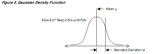
Equally, indiscriminate jitter indicator is recognized to have an uncontrolled amplitude likelihood task that protracts out ad infinitum. The universally employed scientific replicas for this Gaussian probabilistic derivative,
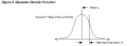
The bounded versus unbounded distinction is rather imperative when regarding the varieties of jitter.
Joining Jitter Elements
Because almost diverse jitter elements are an outcome of unsystematic apparatus, joining them in an accurate arithmetical logic demands the applicability of stochastic functions. Presuming the jitter foundation emerge from independent procedures, which is often the scenario, their probability density functions may be augmented jointly employing intricacy performances. In actual fact, jitter elements and sources are most clustered much less meticulously, in the tune of optimum apex-to-apex worth. It is evenhanded ballpark figure especially when doing the estimates to simply sum the mathematical apex-to-apex worth of the elements. Consider that allocating apex-to-apex worth to an unbounded indiscriminate jitter indicator is somehow arbitrary and presumptuous purpose tail is assumed beyond a certain echelon, B.M. Leiner et al (1999:78-88).
SERDES Jitter Parameters
Collectively jitter functionality of an elevated-speed serial statistical connection is associated by the SERDES compounds at each terminal connection.
Conveyor Jitter Generation
The elevated-speed statistical line driver output ought to perfectly engender a differential statistical indicator that is monitored to the conveyor composition chronometer without monitoring jitter. In practice the SERDES conduct and spin the integrated system without bypassing additional jitter to the statistical indicator. Specifying a perimeter on the permissible quantity of jitter at this summit in a statistical conduit is a first-rate mode to insure cooperative TX jitter presentation. A classic SERDES booster/driver integrated system diagram is shown below, B.M. Leiner et al (1999:78-88).
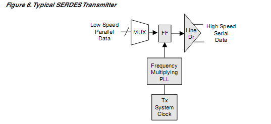
Classically the Tx configuration is a sub-numerous of the serial statistical tempo. The chronometer indicator must be frequency diversified to construct the statistical tempo chronometer indicator that handles the statistical output monitoring gathering. Jitter present on the Tx structure chronometer will conduct by means of the SERDES concurrencies increased segment restricted circle as well as the statistical monitoring cartwheel, at particular echelons. The outcome is augmented jitter at the line driver integrated system. Filled boxes below contain particular analog attributes in play that normally augments some dimension of jitter to a holistic jitter echelon of output indicator. The MUX component, on the extreme end, is a true digital compound and should augment no jitter to the output indicator, B.M. Leiner et al (1999:78-88).
Receiver jitter Lenience
The SERDERS recipient’s capacity to tolerate certain quantities of jitter on the incoming indicator, minus the occurrence of bit identification, is important. A classical SERDES recipient integrated system block structure is illustrated beneath in figure 7.
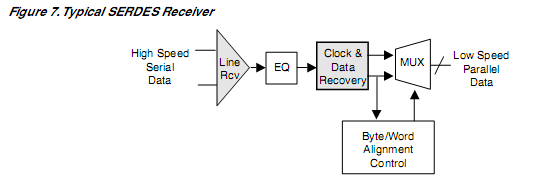
The intrinsically jitter responsive course cylinders that quantify the communal jitter lenience feature are sheltered in figure 7. Blocks that are unsheltered are synchronous chronometer digital courses that will cause extra deprivation of holistic jitter tolerance, when driven by the freshly chronometer associated statistics from the CDR. The bumper amp must accept the in streaming differential statistical indicator in addition to monitoring and also amplitude alteration. Input statistical indicator will transmit straight by means of this phase. A sophisticated bumper enhancer will augment just a slight ration of jitter to the statistical indicator as well as disallowing usual state interference and superfluous indicators, B.M. Leiner et al (1999:78-88).
Additionally to broadcast prominence, the SC gadget offers three dimensions of programmable recipient neutralizer (0, 6db, and 12db) to subsequent recompense for collision of waterway dwindling. Recipient balance is a computation employed at the recipient that usually connects indicator oxidation created by PCB traces, vias terminals as well as protracted communication files. Employing one of the 3 EQ frameworks presents adequate recipient equilibrium agility for most operations, Abbott H.H (2004:20-39).
The chronometer as well as data retrieval circuit (CDR) has the anomaly of rebuilding the received statistical bit chronometer indicator. This occurs with data found in the terminal monitoring statistical conversion. This integrated structure is normally a very suspiciously calculated phase-locked sphere. In practice, it is intrinsically the most important compound in establishing the holistic recipient jitter acceptance performance. Integrated CDR structure monitoring accuracy is retrieving the chronometer has brawny reliance on the statistical transition density as well as on the statistical indicator 1 or 0 mode optimum run extent. Statistical encoding plans as well as statistical scuttling algorithms applied with a SERDES statistic connection can elementarily enhance the statistics trend density and hence enhance Rx jitter lenience, Abbott H.H (2004:20-39).
These approaches are integrated in relatively all specifications that spell out SERDES statistical connections. The regularity substance of the received statistics jitter is a subsequent inconsistent. Collectively, jitter lenience to stumpy occurrence forms of jitter is rather advanced contrary to those one of elevated incidences. The central restriction affecting this phenomenon is closed ring bandwidth of the clock retrieval PLL. Jitter with occurrence content beneath the closed ring bandwidth will essentially be deleted. This occurs since the retrieved chronometer will locate the shift in statistics created by the stumpy occurrence jitter. This can accept the receiver bit detector to correctly read the statistical bit, even when its monitoring has been altered more than one bit interlude, owing to the jitter, Michael Green (2002:102-09).
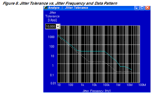
Figure 8 illustrates the jitter lenience vs. jitter concurrencies as well as statistical trend for a nominal LatticeSc gadget, performing at 3.125GBps. Sinusoidal jitter was injected onto the test trend; at enhancing dimensions unit bit errors were visible, Michael Green (2002:102-09).
Power Purveyor Noise Easiness
Power purveyor noise is a feasible foundation of jitter. Digital switching compounds as well as switching power purveyors in a structure emblematically construct elevated echelons of noise voltage on direct current power source ranks. SERDES Tx as well as Rx integrated circuits can prospectively decipher this racket to jitter in the serial statistical connection, Michael Green (2002:102-09). Clatter condensing at the PCB echelon is a proficient mode to avoid this intricacy. Vendors normally present power decoupling recommendations in the catalogue. Certain SERDES item purveyors, like lattice, blueprint significance within the integrated circuit to exhibit elevated supply voltage clutter lenience. This could be realized by interior filtering that hinges on differential integrated systems with towering usual mode rejection attribute.
SERDES mechanism Jitter Dimension Scheme
Precision as well as repeatable jitter dimensions of SERDES mechanisms can be a nagging assignment. The speedy progression of mechanism functionalities at multi-gigabit statistical rates connected with arising novel hardware framework specifications has developed a void for many designer organizations. Importantly, reserves are required to fill this demand and sufficiently support modest SERDES gadgets functionalities. Lattice has acknowledged the requirement and labored to determine proficient laboratory test methods and characterization process. Various test approaches employed are illustrated in this phase, Michael Green (2002:102-09).
In our contemporary existence, 3 forms of multi-gigabit jitter dimension apparatus are normally accessible. They consist of Agilent’s Infiniium DSO 81204A asynchronous towering speed Oscilloscope with jitter evaluation abilities, Agilent’s 86100C digital communication Analyzer with jitter evaluation abilities (DCA-J) as well as the Wavecrest’s SIA3000 interlude interval Analyzer (TIA), DEOG-KYOON JEONG (2002-89-99). All the artifacts support the modern elevated speed dimensional know-how and both present DSP intensive statistical processing as well as extensive SW configuration to carry out very complicated data evaluation and collective jitter putrefaction. These series can collapse a complete jitter dimension into RJ as well as DJ elements as well as subsequent decomposition of DJ in diverse subcategories. Whereas precision jitter measurement is imperative in jitter trying and equipment attribution, other test computations incorporate BER testing and test indicator production are essentially fundamental phases of collective test structure. This is factual in the case of jitter lenience described, that demands that a test statistical indicator be propagated with monitored stable amounts of jitter augmented. The jitter indicators required to incorporate various jitter forms debated afore. Modern jitter specifications prompts for complex jitter test indicator created by indiscriminate jitter as well as two other structures of deterministic jitter. The amount of each jitter element must be independently monitored, DEOG-KYOON JEONG (2002-89-99).
Conclusion
The SERDES function sketch illustrated afore is redrafted in figure 9, depicting important compounds, where jitter is fundamentally developed and hoarded, Jaeha Kim (1997:57-69).

Most of the jitter important compounds are fundamental systems of SERDES crossing point substructures. The significance of the jitter functionality of these sections was stressed. The functionality can be realized if eminent cheap blue print traditions are emulated. In addition of significance is laboratory attribution and confirmation, at both the evolving as well as manufacturing echelons. Fundamental jitter test approaches employed by Lattice to dichotomize SERDES artifacts were defined. The choice for integrated circuits artifacts with acknowledged jitter attributes is monumental in latest functions. Structure blue print that comprehend the revolve of the SERDES compounds in their configurations as well as how they impact collective functionalities will be presented the viable as well as robust functionalities that their clients require. The function of jitter is structure oriented. Lattice presents gadgets analysis boards with elevated speed SMA linkage crossing point. These check planks are accessible to clients so they might analyze items functionality in their fastidious application backdrops. In conclusion extracted HSPICE booster replica is accessible to enhance structure simulation of the important elevated speed serial arrangement crossing point in the appliance, Jaeha Kim (1997:57-69).
References
- Jaeha Kim. Realistic Circuits; Embedded IC Configurations; Seoul National University press; 1997, pp 57-69
- DEOG-KYOON JEONG. Electrical Engineering: embedded systems; Berkeley university press; 2002, pp 89-99
- Michael Green. SERDES and integrated circuits; data communication interface; Berkeley university press. 2002, Pg 102-09
- William Stallings. Data and computer communications University of Harvard press; 2000, pg. 120-34
- Schwartz, M, Computer Communication Blueprint and investigation, 1977, chapter 2 for chronological substance on package switch; IEEE Computer weekly, July 1999; issues 1: Vol 12; pg 70-83
- Schwartz M, Data Diffusion, Transform, and Noise; Elevated Speed Statistical races; IEEE PC systems 6th edition, 1996; pp 10-15
- Abbott H.H; communication Nike Zeus Statistical, plus segmentation of article on the Arpanet after 20 years; pp 20-39
- B.M. Leiner et al, The Yesterday and Tomorrow of the internet, Communications of the ACM, 1999, Vol 45, pp 78-88