Cantenna Design
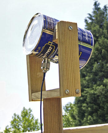
The work of the Cantenna is to act as an alternative antenna, which can extend the range covered by a wireless router. It is a directional type of antenna, which consists of a metal can, coaxial cable with an N-type connector, and an adapter for attaching the coaxial cable to the router itself (Dobkin 97).
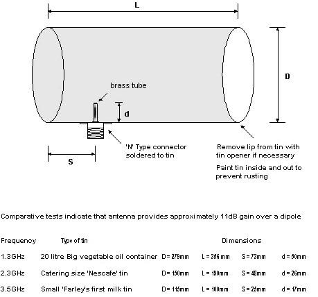
Instructions for building a Cantenna
The first step will involve the collection of materials that are needed in this case. They include a metal measuring three to six inches in diameter, an N-type Female Chassis-mount connector, a cordless drill with 5/8th inch drill bit and other attachments, pigtail to connect the Cantenna to the router, a masking tape, and a ruler. After the collection, the assembling of the materials starts to make the Cantenna.
The Cantenna is prepared by obtaining a clean and empty can, which has one open end. The can should have a radius of about 3.65cm – 4.67cm. Here: r = 3.65cm. In this case, any can between 3 and 6 inches in length is suitable. If the length exceeds this size, there will be a significant reduction in the functioning of the device. Irrespective of the final choice of the can, the ridged types should not be considered as they affect the quality of the signal. After preparing the can, mark the position for drill holes. There are several Cantenna Calculators available online for calculating the dimensions. The “N-connector provides attachment to the pigtail from the router or wireless access point” (Lobo et al. 18). The N-connector requires a 60-inch hole on the side of the can. The position of the drill plays a significant role in the operation of the device especially the wavelengths. The Cantenna Calculator, in this case, helps to determine the position of the hole.
From experiments, a more accurate hole would probably be “1.38 inches from the bottom of the can…by simply using a piece of masking tape and placing a mark at the exact point indicated, a cordless drill can be used to make a starter hole, which can be finished using a half-inch drill bit” (Lobo et al. 21). To ensure nice fitting of the N-connector, “use a special tool to smoothen out the burrs and enlarge the hole slightly and after drilling the hole in the side of the can correctly, place the N-connector into the can and attach the pigtail to the router/wireless access point” (Lobo et al. 24).
After building the Cantenna as described above and connecting it to the wireless router/access point, the next step is to test its performance. Remove the “stock antenna and connect the pigtail to the router…during this stage, it is important to measure the signal strength and signal to noise ratio to see if it is working well” (Lobo et al. 25). This task can be done using the software that comes with the router. Given that the Cantenna is polarized linearly, it should be “rotated until the strongest signal is achieved” (Flickenger 74).
Wind-belt Design
Description of the Wind-belt
Shawn Frayne invented the design of Wind-belt described in this paper. The common wind turbines are not adaptable to small-scale users. Besides, they experience friction in their gearbox and other parts, thus leading to wear and tear. According to Ahmed, with the rotary power, it is not easy to generate under 50 watts (80). Due to this challenge, Frayne studied how vibrations resulting from the wind caused the collapse of the Tacoma Narrows Bridge in Washington back in 1940 (Ahmed 81).
Frayne’s device is composed of a taut membrane, which is fitted magnets in such a way that they move perpendicularly between the wire coils (Manwell, McGowan, and Rogers 103). Model devices have produced up to 40 milliwatts with 10-mph wind speed. This aspect makes the wind belts 10 to 30 times efficient microturbines. Frayne perceives these wind belts as affordable. Besides, they can be used to phase out paraffin lamps in Haitian homes. Frayne’s innovation is not sophisticated, and thus if it breaks, local users can fix it.
Materials required
The necessary materials include a VHS videotape, which acts as a membrane, two pieces of neodymium magnets, and an insulated wire copper coil. The magnets are fixed on the tape by an adhesive. It is a scientific principle that an electric current is generated when a conductor disturbs a magnetic field.
Instructions on how to construct a wind belt
The wind-belt described in the procedure below has a capacity of 1.5V AC with a 20mA current, which is less than the energy needs of the project. To make the frame, a wooden board of about 52 inches long and 6 inches wide is cut. After offsetting 4 inches from each side, 2.25-inch diameter holes are drilled at both ends and the middle between them is cut.
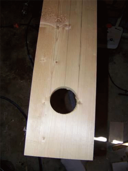
For coil and magnets, three feet of copper wire (12-18-gauge) is wrapped around a pill bottle at half its height. Circular neodymium magnets are then fixed on flexible cardboard, half an inch of its height around it and placed in the pill bottle. The bottle is capped and then placed through the hole made on the wood frame. This procedure is repeated for the next hole. To fix the belt, a strip made from “a plastic bag with the same length as the frame and with width close to that of the frame is prepared” (Lobo et al. 20). Four blocks of wood with a height of about two inches are set with the strip placed in between them. The plastic strip is tightened so that it can vibrate.
To make the structure, the wooden blocks are sandwiched with the belt using the wooden frame. The structure is held in place using suitable screws fastened on each corner of the frame. To align the magnets, four more magnets are used and arranged so that there is an attraction, thus making them stick together on the plastic strip. The other magnets inside the pill bottle are arranged to give out the correct orientation of magnetic flux. To include electronic devices, crocodile clips are added to each end of the copper cables and then connected to a power source for distribution.
The power produced by Wind-belt
In determining the power produced by the wind belt, two assumptions are made about how power produced relating to geometry and the wind speed (Briand et al. 75)
The first assumption is that the power generated is directly proportional to the area of the device. Equation 1 represents this assumption with A as an area of coverage and W as the generated power.

A second assumption is that the power is “directly proportional to the cube of the speed of the wind…if the value of wind speed is doubled, the resulting power output increases by a factor of eight” (Briand et al. 76). This aspect is represented by equation 2 below.

It is necessary to consider the energy produced by the wind. For simplicity, “the equation kinetic energy is used to represent the minimal energy” (Lobo et al. 21). In equation 3 below, “EK is kinetic energy, and m is the mass of the wind” (Lobo et al. 21).

To make this equation more practical, the mass of air is expressed using mass flow with t as time and p as the density. In this case, the final equation of the power produced by the wind belt is given by equation 4.

Air density is usually not an ideal value, and thus it cannot be measured using a wind turbine. Therefore, the ideal gas equation is used so that density is expressed using other values such as temperature and pressure, which are easily measured. This equation also includes the volume, ideal gas constant, moles, and its molar mass (Muyeen 134). By working with the density of air and substituting all these in equation 4 above, the new wind belt power is given by equation 5 below.

The practicality of Wind-belt and Cantenna
There will be two scenarios to consider for the application of the wind belt and the Cantenna devices. The first scenario involves a low-cost feasibility consideration, which targets small schools in rural villages, where the wind belt and cantenna will be used to provide power to a small radio and LED lighting system. The second scenario involves modest cost considerations whereby the wind belt and the Cantenna will be used to provide power to a wireless base station for a selected hospital.
First Scenario: A school
In rural areas, getting a strong signal for Internet connectivity using the normal channels is hectic. Therefore, the option of using a Cantenna increases the probability of accessing the Internet through WiFi.
In a case of providing lighting and communication using a small radio in a school, the power required to run the device is about 15 W, and it costs $15. The LED light bulb requires about 1.3 W at $5.13 (Briand et al. 78). This information is used to come up with a suitable size of the wind belt required by a school in the village. The power output expected from the wind belt is calculated from equation 6 below.
P [W] = 15[w] + 1.3[W] = 16.3[W]……………………….6
This equation is substituted in equation 5 above to calculate the power required from the wind-belt. The following variables are used in equation 5 to design the area of the wind-belt:
- The average pressure of air, P, is 101325 Pa
- The average temperature of the air is 298.15 K
- The average velocity of air at ground level is 7.5 m/s
Using equation 5 and the value of P obtained in equation 6 above, the area of the wind belt is obtained as A = 0.065M2
If a standard size wind-belt measures1M long and 5 CM wide, the number of wind-belts needed per LED bulb and radio can be determined using the equation below.

Therefore, approximately one medium wind belt is required assuming lights are only used at night.
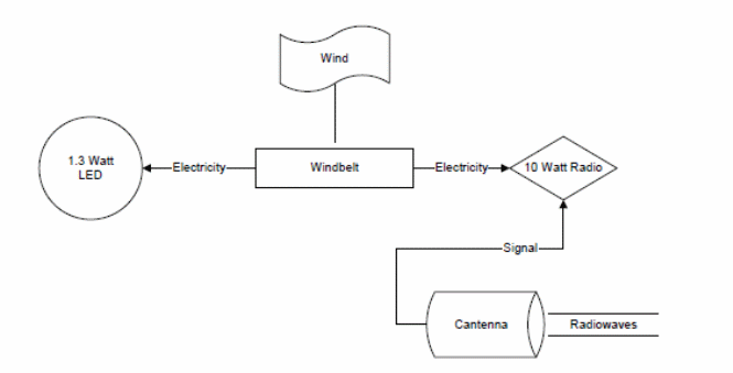
Second Scenario
In this scenario, the wind belt is used on an 8-watt computer with a 2-watt Wi-Fi base transmitter for a selected hospital. Hospitals in rural areas also need to be equipped with reliable technologies to improve service delivery. The design involves inserting the parameters in equation 5. The area of the wind belt is obtained as 0.028M2. The procedure above is repeated to determine the number of wind-belts required. In this case, less than one wind belt (0.56) is required to give adequate power to the computer and the Wi-Fi station.
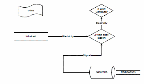
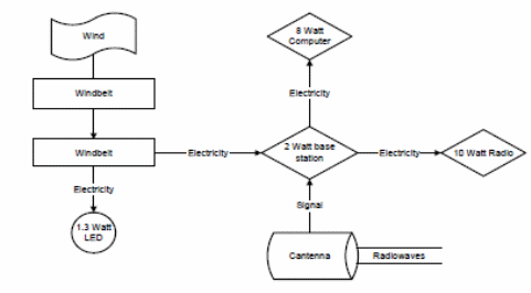
Wind-belt system is simple in construction because in a bid to connect it to power users such as LED lights or battery chargers there is no need for specialized or complicated electronic circuits at the output. Manwell, McGowan, and Rogers posit, “To charge batteries, only simple rectification circuits are used” (108). This system can be adapted to charge a USB-powered device by using a small voltage regulator, which connects directly to the rectification circuit.
Besides being easy to make, the wind belt is inexpensive. This assertion holds because all the materials used are recycled wastes. The necessary materials include a VHS videotape, which acts as a membrane, two pieces of neodymium magnets, and an insulated wire copper coil that can be found locally without incurring any cost. The magnets are fixed on the tape by an adhesive, which is also cheap and locally available.
With Cantenna, it is also simple to construct a network. Many people have started adopting this concept of Cantenna to access WiFi networks cheaply. Individuals make the Cantennas for themselves and find it more cost-effective and dependable in the rural areas where there is limited infrastructure. Anyone can certainly make the Cantenna as long as she or he can follow the documented procedures and the knowledge related to antenna theory. Materials for making this Cantenna such as “N female conductor, screws, nuts copper wires, bolts, and several electrical applications for drilling, are also locally available” (Lobo et al. 25).
This cheap technology provides an option for online users who are practical, and they hope to grab the highest WiFi range in their point of location. Just like the wind belt, the Cantenna is cost-friendly. This assertion holds because the materials used can either be collected from unwanted electrical wastes or be obtained from the local shops.
Final Solution
In the final solution, the project will have three main components:
- Computer
- WiFi network (Cantenna-based)
- Wind-belt Generator
Estimated costs and power requirements
The Power System
A wind belt array will be commissioned and tested on the grounds for about 60 days (Lobo et al. 27). In addition to the wind belt components, the system will also require a power control system and means of energy storage.
Wind-belt Array – This array will supply the energy required on the site with the components. According to Humdinger’s medium wind-belt, the site would be required at least 33 individual medium-size wind-belt modules (Lobo et al. 26).
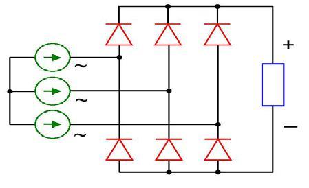
Controller Circuit – The system would need a controller to regulate fluctuations in the electricity. The controller also converts the AC to DC. This controller also acts as a sensor for the voltage and directs the excessive charge from the battery. The rectification circuit is made up of four diodes. Several bridge rectification circuits can be connected in parallel if the wind-power system generates too much power.
Energy Storage
Since this project might be carried out in a remote area, which is not connected to the national electricity grid, there have to be ways of storing the power generated by the wind-belt. Energy storage units are included in a separate wind power system to smoothen the variations of the frequency of electricity caused by varying wind conditions. The storage components also “store excess electricity by charging the module when there is excess generation exceeding consumption (e.g. at night or during the periods of strong wind speeds)” (Lobo et al. 28). The storage devices also discharge the energy stored when there is insufficient speed to meet the energy demand (Moseley and Garcia 106).
This project will use lead-acid accumulators, which are also known as deep cycle batteries. These batteries tolerate situations where heavy loads drain almost all the charge from the battery. One particular type of lead-acid accumulators is the Absorbed Glass Mat (AGM) batteries. The characteristics and advantages of AGM batteries are outlined below. The only challenge of AGM batteries is that they require high initial capital investments (Gonzalez-Prida and Raman 88). However, given that they are safe and maintenance-free, they become a viable option for communities learning “how to maintain a wind-powered electricity system” (Menictas, Skyllas-Kazacos, and Lim 114). The following are the advantages and characteristics of AGM batteries relative to the project.
- They have a high density of energy, which increases their energy storage capacity.
- They experience low resistance and thus they do not overheat during heavy charging or heavy loads.
- They employ recombinant technology for batteries, which involves recombining oxygen and hydrogen inside the battery. This aspect minimizes the loss of water from the battery, hence eliminating high maintenance costs.
- The acid inside the battery is kept in a glass mat of boron silicate, which ensures that the battery will not leak if it is broken. This aspect makes the battery safe to use.
- The batteries’ standby discharge is slow. Therefore, it is possible to store them for a longer period as compared to other lead-acid batteries.
Works Cited
Ahmed, Siraj. Wind Energy: Theory and Practice, New Delhi: PHI Learning, 2011. Print.
Briand, Danick, Eric Yeatman, Shad Roundy, Oliver Brand, Gary Fedder, Christofer Hierold, Jan Korvink, and Osamu Tabata. Micro Energy Harvesting, Weinheim: Wiley-VCH, 2015. Print.
Dobkin, Daniel. Rf Engineering for Wireless Networks: Hardware, Antennas, and Propagation, Amsterdam: Elsevier/Newnes, 2005. Print.
Flickenger, Rob. Wireless Networking in the Developing World: A Practical Guide to Planning and Building Low-Cost Telecommunications Infrastructure, Florida: Orange Grove Texts Plus, 2009. Print.
Gonzalez-Prida, Vicente, and Anthony Raman. Promoting Sustainable Practices through Energy Engineering and Asset Management, Hershey: IGI Global, 2015. Print.
Lobo, Allister, Evelyn Mukwedeya, Thamiso Kgati, Kelvin Guobadia, Billy Dega, and Raymond Gomashi. Implementation of Wi-Fi Network in Rural Areas Using Windbelt-Cantenna Technology 2010. Web.
Manwell, James, Jan McGowan, and Anthony Rogers. Wind Energy Explained: Theory, Design, and Application. Chichester: Wiley, 2009. Print.
Mental, Chris, Maria Skyllas-Kazacos, and Mariana Lim. Advances in Batteries for Medium and Large Scale Energy Storage, Boston: Elsevier, 2015. Print.
Moseley, Patrick, and Jürgen Garcia. Electrochemical Energy Storage for Renewable Sources and Grid Balancing, Amsterdam: Elsevier, 2014. Print.
Museen, Sumaiya. Wind Energy Conversion System, London: Springer, 2011. Print.