Introduction
Aerospace engineers designing spacecraft and missile systems do most of their tasks in workshops. The profession value accuracy in handling tools and taking measurements of specific materials. However, in some cases, the specialists are exposed to mild accidents that can escalate to more significant risks if not controlled. Such accidents originate from chemical spillage, fire outbreaks, electric shock, and tool default. Nevertheless, the experts undergo training to enhance the precautions and procedures for handling workplace accidents. I think digital drawings are essential in aerospace engineering; however, the job is risky based on the types of accidents attached to the profession. In my view, uncontrolled accidents in engineering can be reduced through active training of new workers in risk management, techniques of safety measuring, and conceptualizing projection concepts.
Discussion
Aerospace engineers encounter different forms of accidents in their workspaces. The fitting of safety equipment and exposure of workers to preventive measures to reduce accidents in engineering workshops does not limit the occurrence of such risks. According to Sahu (2022, p.187), the differences in the types of accidents, demand varying procedures in controlling extra damages. In the event of a fire outbreak in offices, people are recommended to raise the alarm, summon fire brigades, and evacuate the building in this chronological order. The evacuation policy of workshop fires requires experts to switch off operating devices to minimize further fire hazards (Hopkin et al., 2022, p.53). Workers should not regain entrance to the burning workshops as firefighters continue their tasks. Instead, they should report to fire assembly points and only participate in the event with the guidance of the experts.
Management of electric shock and chemical spillage accidents differs from workshop fire prevention policy and procedures. In the event of electric shock to human operators, aerospace engineers in the building must turn off electricity from the main switch. As the communication team alerted 911 for a response, nobody should touch the injured person in contact with the electric point. Sahu (2022, p. 192) highlighted the significance of CPR chest compressions in events where the victim lacks circulation or movement. Having a fire extinguisher in place assists respondents in the eventuality of fires; therefore, water spills should be controlled after cutting electricity. For chemical spillages, Sahu (2022, p. 186) argues that notice serves as the first step in preventing further damage from chemical accidents. The step of notifying other members about the emissions promotion safety. Placing proper personal protective equipment (PPI) for response teams protects them from direct contact and inhalation of hazardous chemicals. The PPIs should then be used to stop the source of the spills alongside proper absorbent materials.
Machine use exposes workers to many challenges, risks, and advantages. Although tool accidents result from negligence and carelessness, sometimes equipment failure leads to uncontrollable risks. Understanding the usability of a device requires the analysis of key tool components. Specific precautions aid the utility, maintenance, and storage of tools; as a result, the safety measures incorporated in cutting and mental removal are different from dismantling and precision measuring tools. Abdelrazek (2020, p. 4224) echoed that when handling cutting and mental removal tools, users must avoid touching the cutting edges to reduce injury rates. In addition, employers handling the cutting tools must avoid mismatching and misusing metal removal equipment. Milling cutters should also consider vibration. The care for cutting and mental removal tools occurs when such objects are kept in dry places. Cleaning, inspecting and maintaining cutting tools promote such materials’ efficacy. Cutting tools with loose, cracked, and broken edges should not be used by operators.
Dismantling tools also expose workshop employees to uncontrollable risks if not properly handled. Wearing PPIs like helmets, gloves, and safety shoes boost the safety of operators controlling assembly tools. Employees must have glasses to reduce excessive lights that might harm the eye and noise protective devices to limit the damage to the eardrum. Furthermore, training workers on the dangers of assembly tools improve awareness among affected groups. Unlike dismantling and cutting tools, precision measuring tools require a lot of cure and accuracy in their use and storage. One must ensure that the instruments do not jostle against each other when stored. According to Loignon-Houle et al. (2020, p. 264), precision measuring materials operate best when placed in padded cases multiple reading of results and data.
Measurement of variables in aerospace engineering prioritizes accuracy. Any arising error may result in future accidents and malfunctioning of tools. The knowledge of measurements promotes innovation in the use of digital tools. Metric Vernier Caliper (MVC) and imperial micrometers take specific measurements in the current engineering occupation. Metric Vernier caliper aids the measurement of internal and external distances; it is advisable to check the defaults of the vernier before use to confirm its state. When the mouth of MVC is damaged, the tool’s accuracy reduces. The second face to incorporate when using the MVC involves the observation of the major scale; it should remain on a ratio of 1: 100 (Loignon-Houle et al., 2020, pp. 245-246). MVC uses the vernier and significant scale to compile measurements. For instance, if the graduation of an MVC is 0.05, the final measurement of distances is attained by adding the vernier and primary scale readings.
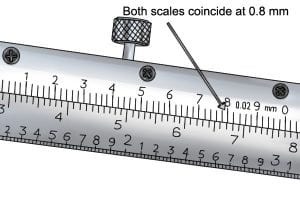
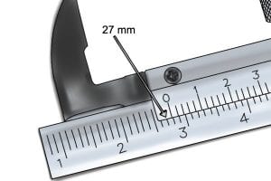
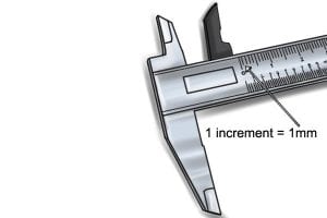
The number following the zero mark to the left constitutes the figures of the main scale value. MVC measurements have a range of one millimeter (1mm). In this case, the main scale measurement is 27 mm, while the vernier scale indicates a reading of 0.8. As a result, the total distance measured by the Metric Vernier Caliper equals 27 + 0.8 = 27.8mm. The single increment in the scale indicates the smallest values recorded in the major scale measurement kit.
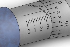
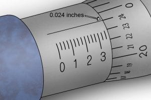
The imperial micrometer (IM) measurement scale is different from MVC. The smallest values in IM can be read on the sleeve scale of zero-point zero-two-five (0.025) inches (Burbidge, 2019b). Locating the smallest scale in IM occurs by reading the immediate number to the left of the thimble. The secret of recording data from the IM lies in the alignment of the number in the index line on the sleeve scale. For instance, the number immediately after the index line becomes the readings if two variable falls between the scale. Summing the values in the sleeve, thimble, and vinier results in the total measuring value of the IM. Figure 4 below shows a measurement of 0.35+ 0.024 = 0.374 inches.
Engineering professionals associate with numerous drawings in the development of new inventions. Sankey, assembly, erection, and instrument drawing are some of the standard engineering drawings witnessed in the Aerospace business. Erection diagrams include dimensional data and general configuration information; such drawing is relative to their adjacent and structure items (Melani and de Souza, 2020, p. 43). Erection diagrams have key components that distinguish them from other engineering pieces. The figures have pipe interfaces, assembly drawing references, and principal dimensions.
Assembly diagrams include all the figures characterized by configurations and item contents. Assembly diagrams reflect the logical levels, deliverability, testability, and functional descriptions of objects, and they happen in more than two parts. Assembly diagrams are essential because they help engineers identify every item’s constituent. On the one hand, instrumental drawings show the process flow of pipes and vessels alongside the control devices. While on the other hand, Sankey diagrams are the visualization incorporated in depicting set values.
The design of aerospace vehicles has been a long-term dream for engineers. The specialists in the technical field have developed the latest sketch and uploaded the diagram on hard-copy computers. In the figure Mica et al. (2019, p.768), the aerodynamics perspective indicates the airplane’s features. The wing size allows the aerospace vehicle to circumnavigate the atmosphere with ease.
The first angel and third angel projections are different in many ways. First angle projections are placed in the first quadrant, while the 3rd angle is placed on the third line. In addition, the 1st angle projection is positioned at the top of the horizontal plane and back of the vertical one, which is lacking in the third angle. According to Rathnam (2017, p. 84), 1st angle projection is opaque, while the third one is transparent. The left view is placed on the left side of vertical axes in the third angle projection, whereas it appears on the right side in the case of 1st angle projection.
Conclusion
I think aerospace engineers encounter numerous risks in the workshops than office employees. I perceive that the professionals are trained to handle rising issues like fire, chemical, and electric shock accidents. I respect aerospace engineers because they are skilled in drawing digital diagrams, measuring accurate distances, and maintaining work tools.
Reference List
Abdelrazek, A. (2020) ‘Metal cutting lubricants and cutting tools: a performance improvement and sustainability assessment review’, The International Journal of Advanced Manufacturing Technology, 106(7), pp.4221–4245.
Burbidge, R., (2019) ‘How do you read a metric vernier caliper’? [WWW Document]. Wonkee Donkee Tools. Web.
Burbidge, R., (2019b) ‘How do you read an imperial micrometer’? [WWW Document]. Wonkee Donkee Tools. Web.
Hopkin, D. et al. (2022) ‘Large-scale enclosure fire experiments adopting CLT slabs with different types of polyurethane adhesives’, Genesis and Preliminary Findings, 5(39), pp. 37-68.
Loignon-Houle, F. et al. (2020) ‘Experimental validation of a coincidence time resolution metric including a depth-of-interaction bias for TOF-PET’, Physics in Medicine and Biology, 65(7), pp.245–275.
Melani, A. and de Souza, G. (2020) ‘Mapping SysML diagrams into bayesian networks: a system engineering approach for fault diagnoses’, ASCE-ASME, 6(2), pp. 45–78.
Mica, L. et al. (2019) ‘Developing a visual analytics tool for polytrauma patients: proof of concept for a new assessment tool using a multiple layer sankey diagram in a single-center database’, World Journal of Surgery, 44(6), 764–772.
Rathnam, K. (2017) Orthographic projections, in the first course in engineering drawing. Singapore: Singapore Press.
Sahu, D. (2022) ‘The effective criterion for equipment management in the construction industry’, in Das, B.B., Gomez, C.P., and Mohapatra, B.G. (eds) Recent developments in sustainable infrastructure (ICRDSI-2020)—structure and construction management. Lecture notes in civil engineering, vol 221. Singapore: Springer Nature, pp. 185–199.