Introduction
“Design for the next Generation “superjumbo A380” ultra-high capacity commercial transport airliner”
A close observation of an aircraft reveals a number of visible features from a facial appearance. The observable features include wings, the propeller engine and the tail. A more detailed observation beyond the visible details exposes hidden and very intriguing features. All these features, both visible and invisible, form the whole aircraft structure and enable it to perform the designers intended functions.
Aircraft conceptual design is an art as well as a science, put in a theoretical perspective. It is the paper-based or computer-designed logical engineering procedure of creating a flying machine to satisfy particular user specifications and manufacturers requirement. It is also essential as a tool for expressing pioneer innovation, with the inclusion of newly discovered technological ideas. (Anderson 2005, p. 37).
Just to mention an example of a conceptual design is the 1947 Bell X-1commercial transports, the pioneer rocket driven aircraft to surpass the speed of sound in climbing flight. The process is an essential tool for a manufacturer to realize successful airplane designs, which can compete with the dynamic progression in aeronautical Engineering.
New design Definition
The conceptual design is the graphical representation of structures of various fundamental features in the area of aeronautical engineering. These areas include propulsion, taking off and landing control, aerodynamics and weight control. The design takes care of the size, weight, shape and the speed of an aircraft.
In order to design a better performing aircraft, it is vital to balance all the aspects without a compromise (Anderson 2005, p.21). While observing the balance, the designer ought to be able to optimize at least one of the design factors depending on the purpose of the aircraft, the desired cruise speed, flight range, take-off distance, standard cruise altitude, The Federal Aviation Association (FAA) Regulations.
The mission or purpose of the aircraft
The design of a new aircraft begins by identifying its mission, which can include military missions, transportation and space study. The Super Jumbo that we are designing is strictly meant for commercial transportation. It has to take into account the size depending on the number of people it intends to transport per flight, the fuel capacity, the distances between the airline’s destinations.
It should have a capacity of between 800 Pax to 1200 Pax. This is a modern commercial transport aircraft; therefore, its design has to comply with the international transport requirements to serve the future market demands. (Anderson 2005, p.20). Optimizing all elements of aircraft performance is not a guarantee, so one element has to be selected as the most vital. In this case, the mission of the aircraft plays the key role in guiding the entire design process.
Maximum Speed and Cruise Speed
The superjumbo A380 being a high capacity aircraft has to be propeller-driven to cruise at speeds between 800 ft/min to 800 ft/min. This is an optimum cruise speed range necessary for maximizing the payload weight and the average speed. The Superjumbo commercial aircraft cruises at a supersonic speed.
Has a longer range and heavier payload. The cruise Mach number of this Superjumbo is 0.82. It will carry 150 passengers operating at arrange of range of 3860 miles, which is within the optimal range of the aircraft of a standard class. The maximum speed is specified as having a Mach number that is on average in the range of 1.2.
Standard Cruise Altitude
Usually, the cruise altitude of an aircraft is determined by its cruise speed and its mode of propulsion. Superjumbo A380 is an aircraft with a pressurized cabin, with a propeller engine so it would cruise at 11,500 feet and above. The higher cruise altitude will imply that it will also cover longer cruise ranges.
Flight Range
Flight range is the longest distance an aircraft can fly without need for refuelling. The range has a significant impact on the take-off weight of an aircraft; consequently, it has to be chosen under critical consideration. The Superjumbo A380 is intended to fly from Melbourne to Los Angeles, a distance of 7,931 miles at a supersonic speed. It means the aircraft will require a minimum range of between 8500 to 9200 nautical miles to be safe.
Take-off and landing Distance
The take-off distance of an aircraft is the length of the runway the aircraft will need in order to accelerate and lift off. The suitable distance will be between 6500-7200 feet. This distance will also enable it to climb to its obstacle height of 80 feet. The take-off distance is dictated by different factors such as the maximum lift to weight ratio and thrust to weight ratio.
The landing distance is the length of the runway needed to descend, touchdown and then break to a stop. For the Superjumbo A380, it has to descend from an altitude of 80ft.Its landing distance is determined by the fuel capacity but it is less than the take-off distances.
Federal Aviation Association Regulations
Federal Aviation Association has set standard regulations, to which every aircraft design must comply. The regulations are periodically reviewed to integrate supplementary requirements that emerge because of live experiences with existing aircrafts.
The regulations govern the Air Worthiness conditions of aircrafts, Flight Rules and General Operations Standards, aircraft capacity and the highest takeoff weight. The design of Superjumbo A380 has taken in to account all the design phase regulations, and given provision for the operation regulations to be observed at test phase and the operation phase.
The Process of Design
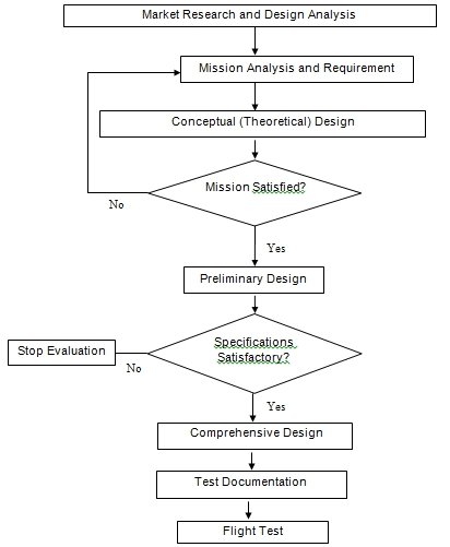
The process of in designing the Superjumbo A380 aircraft from the preliminary conceptual stage to the flight test stage is made up of progressive phases. The first phase is the identification of the desired potential for a new aircraft, apparent market demand and the state of technology (Raymer, 2006).
This phase involves research into the issues affecting the global aviation industry. The objective of the new design is to produce competitive performance to outshine the existing competitors (Sobester, Keane, Scanlan, and Bresslof 2005, p. 7). The second phase is to formulate a conceptual design to develop the principle graphical representation of features and configuration for a proposed new aircraft.
It involves the approximations of the size dimensions, weights and the selection of aerodynamic properties suitable for the satisfaction of the requirements as described in the proposal of the aircraft design. The design will determine the best provision for payload, wing and engine structure.
This conceptual design locates the standard weight categories in order to meet constant requirements. It will determine the modalities for achieving a preferred level of manoeuvrability. The conceptual design is dependent on the mission requirements, as set in the drafted design proposal.
At times, these requirements are not easily obtainable. To that effect, they may need to be realistic. The flow chart shows the flow of activities with mutual dependence between subsequent stages. It shows an iterative loop of sequences and their determinant conditions. For example, when the mission requirements are found to be satisfied, the next phase takes over, which is the preliminary design.
Design Proposal
Our proposal is to design a supersonic long-range commercial transportation business aircraft with a cruise Mach number of 0.82 and a cruise altitude of 11500 Feet. Its range will be 9200 Nautical Miles and a full payload consisting of passengers and luggage of total maximum weight amounting to 8400 kilograms.
The internal layout will be designed to be able to accommodate from 100 to120 passengers. Including the cabin crew, the weight goes up but to a negligible margin, which it can comfortably tolerate. The aircraft will have a maximum takeoff weight is estimated 40000 kg (Roskam1990, p34). It will have wings with split type flaps capable of demonstrating high efficiency in aerodynamics.
The entire body will be very light of weight. It will have a high L/D ratio of above 18 and above for the efficiency of its wings. Its fuel consumption will be as low as below 0.36 so that it can serve as a long-range aircraft. The low fuel consumption will be an added advantage over the many competitors.
The principal design drivers are the high L/D ratio, lightweight and low fuel utilization. The minor design factors are average take-off distance and landing distance, similar to high-speed supersonic Boeings. During the preliminary design stage, a comprehensive analysis will be done on the aerodynamic loads as well as the weights of the component. The comprehensive design will involve generation of a well-designed structure of the Superjumbo A380aircraft. This will consider every detail necessary for building the aircraft.
Theoretical (Conceptual) Design
In this article, we cover an overview of the steps of the conceptual aircraft design of an aircraft. It is further simplified in to numerous items in their order of protocol. These items include Literature review, Initial data sampling, Approximation of aircraft weight, estimation of maximum take-off weight, determination of the weight of an empty aircraft and Fuel tank Capacity.
The other elements, which are rather minor, are the determination of vital parameters of performance such as the Wing area, the wing load, Lift and drag coefficients, Engine selection. Power loading, Performance curve, Thrust to weight ratio, wing loading and the three dimensional model.
The formulation of these elements is exemplified in the subsequent surveys consisting of high-speed long-range supersonic commercial transport aircraft. In order to achieve the mission requirements of the design, we use a good example requiring an element of compromise, since these missions are not easily achievable.
The objective of this conceptual design is to ensure the Superjumbo A380 is built by the year 2025, therefore the time factor must be observed in the implementation of design processes. Below is the conceptual image of the various vital components.


Data acquisition
Data Collection Methodology
Data collection was done from the existing market analysis, the existing aircraft models and from the already completed proposal. Using the L/D ratio projections and simplified thrust data from previous testing, the advanced groundwork design was simulated in the initial mission model. Data was collected for the estimated performance of the existing models, and principal payload test. The payload was also used to estimate the entire System weight, fuel usage and wing geometry and tail surface area using historical data.
Engine size
The data determines the Aircraft sizing as compared to an existing engine type. The engine can be either fixed engine (whose size and thrust are known) or Rubber engine whose thrust can be adjusted while holding T/W constant as the weight varies. Refined sizing approach based on previous method.
Empty weight (W0)
Taking aircraft weights in the perspective of mission as f (W0), we use an iterative method by guessing and solving the values of W0 as:
W0=Wcrew+WFixedPayload+WDroped Payload+ (WFuel/W0) W0+ (WEmpty/W0) W0
Updated method takes into account enhanced statistical equations for optimized factors such as better L/D approximations, ability to provide details of drops in payload and the ability to be applied in the sizing of fixed-engine. When the empty weight of an aircraft (Wempty) is estimated by the use of enhanced statistical equation, it results into more suitable statistical proportion to data. These data includes main design variables such as AR, maximum speed, T/W and W/S, and are related in the following model:
WEmpty / W0 = a + bW0C1 (AR) c2 (T / W0) C3 (W0 / S) c4 MmaxC5
The table below contains sample data collected followed by a computation of empty weight.
Table 1: Computation Parameters for Aircraft Weights.
Configuration Outlook
The first graphical representation is based on the preliminary structure showing the location of main internal components. The real design layout will require a computer aided Design software, for advanced drafting and geometric computations. Actual design outlook will include the locations of the major internal elements, Three-dimensional model projection, fuel carriage, cross-sectional view and volume planning.
Fuel weight
To estimate the fuel weight we use weight-derived fractions. As the aircraft moves from take off to landing, it is noted that there is an amount of weight loss entirely as a result of fuel consumption. The weight of the aircraft at the end is less than at the beginning except in cases where there was refuelling.
This brings confusion in the determination of payload drops, unless the two are computed separately (Raymer 1989, p17). For a near accurate computation of payload drops, it is necessary to improvise the approach to monitor fuel weight separately from the payload loss, remembering to add six percent to the totals for reserve stock and trapped fuel.
W Total Fuel=1.06* Sum (W Fuel)

Strakes and Fuselage
The fuselage of an aircraft does not generate significant lift owing to its long and streamlined nature. In essence, the fuselage shape is considerably different from the airfoil shape of the wing. The wing curve slope for a wing with strake is modeled as: CLa (With strake) =CLa (without Strake) (S+S Strake)/S
Where a is the angle of attack, Sstrake is the surface area of the strake that is exposed, Fuselage for most of the aircraft models is sized by the real world situations and aircraft missions. Another ratio that is equally vital for thermodynamics is the Fineness ratio. This refers to the ratio of length to diameter of the fuselage. The optimal ratio for this by calculation is 14 for supersonic designs. The following table contains data useful as design guidelines.
Table 2: Strakes and Fuselage.
Aircraft Drag
The Drag for a whole aircraft is categorized as either a parasite drag or drag owing to lift. The parasite drag on the aircraft is the friction experienced when the aircraft is not generating lift. Example is the pressure drag or the friction on the surface configuration of the aircraft.
The drag owing to lift includes all manner of frictions which rely depend on the weight of lift the aircraft is generating (Mattingly, Heiser and Daley 1987, p28). These types of drags include drag induced by downwash, the pressure drag owing to forward movement especially at the points of separation. The general model for computing the drag coefficient is expressed as:
CD=CD0+k1CL2+k2CL
Where k1is 1/ (eoAR) and k2 is a variable for generating wings with airfoils, which generate minimum drag while at no lift. CDo is referred to as the coefficient of the parasite drag. The subscript “0” implies that it is generated when there is zero lift.
Parasite Drag
Parasite drag predictions depends entirely on drag data extracted from aircraft designs. A good estimate of supersonic parasite drag may be made using the surface-friction drag coefficient, Cfe, defined in the following model:
Cfe=CD0(S/Swet)
The table below shows a data for the most common values of Cfe4.
Determining an aircraft weight
Purpose
To determine of establish the basic takeoff weight, empty weight and fuel weight of the aircraft during the process of designing through various numerical procedures.
Methods and Equipment used
- Fuel and weight fraction method
- Tables and charts from study books and history
- Survey data
Procedure Followed
- Using a sheet of paper to describe the mission specification in details.
- Prepare a drawing of the mission profile segment clearly.
- Using the above charts continue with the rest through the weight fraction and the fuel fraction method in order to achieve the stipulated objectives.
Mission Description
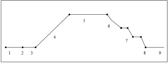
Prepare a graphical representation of the simulated path and the phases the aircraft will undergo from the start of the flight to the landing.
Description:
- Stage 1: Engine starts off and warm-up.
- Stage 2: The aircraft accelerates.
- Stage 3: The aircraft takes off.
- Stage 4: The aircraft begins to climb and cruise altitude while accelerating to attain suitable cruise speed.
- Stage 5: The aircraft has attained the suitable cruise altitude so it Cruises to the destination.
- Stage 6: This is the Loiter phase.
- Stage 7: Flying to a suitable landing height.
- Stage 8: Aircraft Descending.
- Stage 9: Landing and taxiing to shut-down.
The process of mission analysis and sizing usually require iterative actions in any design process. It often requires computer-aided design, by using software known as Aerodynamics. It allows the user to input his or her design mission data items and waits for recommendations to make changes on the designs in order to optimize performance. (Mattingly, Heiser and Daley 1987, p14). The user gets an instant feedback concerning the impact of mission design change to the mission performance. This enables the process of rapid optimization of a particular design idea for preferred performance on any given mission.
Approximation of critical performance parameters
Aim
The aim is to calculate the Critical performance parameters such as (CL) MAX, L/D, W/S and T/W. To determine these parameters we will use vital aspects of performance as maximum speed, climb rate, range, ceiling, landing distance and Take-off distance.
Equipments and methods used
- Regulated – False Method
- Reference to Airfoil sections
- Preparation of Specification chart
- Computation of Jet airplane performance equations
- Charts and tables from references
- Previous performance history
Procedure
Maximum Lift Co-efficient (CL) Max
At this stage, we select the airfoil shape for the Super Jumbo jet aircraft wing using the references obtained from the literature survey and through websites. At the end of the six-series section, airfoil design more specialized for particular applications. Airfoils had good lift capability and low drag sections. The wing design started with the determination of much airfoil sections. The entire geometry is customized depending on its Three-dimensional outlook.
The wings
The determination of body weight and the anticipated volume is done in consideration of performance data, from the history of previous models of aircrafts of similar properties. This is done by computing the ratio of weight to the scientific area of coverage or area in touch with resisting forces (thrust).
For example, the surface plan of an aircraft is in tough with thrust aircraft wings and other control surface areas, the area of coverage refers to the surface plan form. It is possible to predetermine the anticipated weight of the aircraft’s wings and use them to calculate the ratio of weight against thrust, hence the performance capability of the engine.
Gravitational effect
The laws of gravity play vital roles in aiding the decision-making on how to balance the weight of the whole structure. The location of the centre of gravity can always be alternated by the systematic arrangement of payloads. During a normal cruise, the aircraft rests on neutral position in relation to the centre of gravity. While taking off, the aircrafts is resisted by gravity and atmospheric thrust. Nevertheless, during landing, it is entirely resisted by the force of gravity. When the aircraft is cruising
Thrust to weight ratio
The thrust to weight ratio, maximum lift to weight ratio and the air surface friction usually determines the take of distance and the landing distance. Owing to the massive payloads and reasonable wing loading, a gigantic amount of thrust is required to attain the 80 ft takeoff distance as per the requirement. An optional form of the sizing equation expresses the weights of different components in consideration of weight fractions (Megson1999, p18). For this model, several components are used for example the mission fuel and other weight fractions.
Engine Selection
A lot of care needs to be taken when deciding on the engine to be used. Engine controls fuel consumption it has a direct relation to the aircraft range, endurance and payload. The Superjumbo aircraft will have a high power loading value compared to other ordinary propeller engine aircrafts. While selecting an engine, it is necessary to select one, which will not fail to absorb enough air At the same time, it should be protected from pulling in foreign bodies such as birds of the air.
Design Data
We will use the data for lift and drag for the superjumbo as described in the previous sections to and the engine data as the aircraft models. The table below shows some of the design data that will be taken into consideration:
Conclusion
Upon performing several meticulous steps of arithmetic analysis we concluded that our Super Jumbo aircraft has the above information as and the values as stated below:
- (C L)MAX (Maximum Lift Coefficient) = 2.43
- (L/D)MAX (Maximum Lift to Drag ratio)= 16
- (W/S) (Wing Loading)= 392.996 kg/m2
- (W/T) (Power Loading)= 496.5 kg/kN
Performance curves: Charts & Calculations
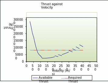
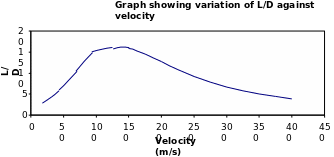
To draw the various charts to represent the estimated values of the performance parameters of the proposed Superjumbo aircraft whose design is underway. This is to provide a vivid interpretation of the data after collection and analysis.
Graphs
![A graph showing variation of Altitude at different [R/c] MAX: ratios.](https://ivypanda.com/essays/wp-content/uploads/2019/04/39133_9.gif)
The V-N Diagram
To sketch the V-n diagram representing the long range high speed flight for commercial transport business jet. The formula applied takes two forms as follows:
- n=L/W
- n = [C 1-Max (1/2) PV2 * S] / w
- V = √(2nW)/ C 1-MaxPS
This V-n Diagram is pictorial representation of the two canard coefficients CL and CZ. It exist inform of a chart, with lines representing the data dependency between two variables. The equation V=Vc represents the maximum lift amount which the wing produces at different values of velocities.
3-D Impression
To display the 3-dimensional impression of the actual aircraft, that is how it will appear when it is finally ready for use.


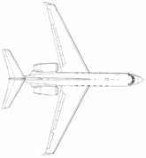
As seen from the conceptual design results, the expected configuration of the Superjumbo A380 is the ideal one for the described mission. This configuration generates minimal drag owing to the smaller tail and smaller landing gear. This configuration also produced lightweight, implying that it will require less lift while performing the desired mission.
The aircraft will not necessarily require adjustment because it will be subjected to thorough quality assurance test such that it will be perfected before it comes to Market by the year 2025. The test will also be compliant to the Federal Aviation Regulations concerning the aircraft operation. This design is reliable and easy to learn and use.
User Documentation
Being a new model, there will be a user operation manual for controlling the specific unique features. The manual will contain the instructions of the do’ and don’ts while in the aircraft. Among the vital information in the documentation, there will be weight limits to safeguard the aircraft against violation of payload policies described by the Federal Aviation Association Regulations.
Secondly, there will be maintenance instructions to protect the aircraft from wear and tear. Thirdly, there will be technical description of the aircraft, including thrust, maximum fuel capacity, range, endurance, payload and the maximum cruise speed.
References
Anderson, J. D., 2005. Introduction to Flight, 5th ed, McGraw Hill, New York.
Mattingly, J.D., Heiser, W.H., and Daley, D.H., 1987. Aircraft Engine Design, AIAA Education Series, Washington, DC.
Megson, T. H. G., 1999. Principles of Stressed Skin Construction,” Aircraft Structures for Engineering Students, 3rd ed, Butterworth Heinemann, Oxford, England.
Raymer, D.P., 2006. Aircraft Design: A Conceptual Approach, 4th Edn, AIAA Education Series, New York
Raymer, D. P., 1989. Aircraft Design: A Conceptual Approach, AIAA Education Series, Washington, D.C.
Roskam, J., 1990. Airplane Design Part VIII, Roskam Aviation and Engineering Corp, Ottawa, KS.
Sobester, A., Keane, A., Scanlan, J., and Bresslof, N., 2005 Conceptual Design of UAV Airframes Using a Generic Geometry Service AIAA, USA. Superjumbo A380 pg